background image

4.2  Remote mounting

The standard flow transmitter enclosure is a powder-

coated, aluminum, IP67 explosion-proof enclosure. 

Typically, the enclosure is mounted as close as possible 

to the transducers. When choosing a site for a remote-

mount installation, which is recommended for process 

temperatures exceeding 150°C, make sure the location 

permits easy access to the enclosure for programming, 

maintenance and service.

Attention!

For compliance with the European Union’s 

Low Voltage Directive, this unit requires an 

external power disconnect device such as 

a switch or circuit breaker. The disconnect 

device must be marked as such, clearly 

visible, directly accessible, and located within 

1.8 m (6 ft) of the transmitter.

4.3  Cable lengths

Locate the flow transmitter as close as possible to the 

transducers. The maximum distance from the transducers 

for remote mounting is 1000 ft (300 m) using RG-62 coaxial 

cable or equivalent. If longer distances are required, consult 

the factory for assistance.

4.4  Transducer cables

When installing the transducer cables, always observe 

established standard practices for the installation of 

electrical cables. Do not route transducer cables alongside 

high amperage AC power lines or any other cables that 

could cause electrical interference. Also, protect the 

transducer cables and connections from the weather 

and corrosive atmospheres, and be sure to follow the 

manufacturer’s installation guidelines if cable glands are 

provided.

4.5 Insulation

Do not place thermal insulation on or around the transducer 

locations or the flow transmitter. The enclosures act as heat 

sinks that protect against high and low temperatures.

4.6  Vibration exposure 

considerations

Whenever possible, install the flow transmitter in a location 

isolated from vibrations. Avoid installing it near equipment 

that generates low-frequency, high-energy random 

vibrations.

4.7  Sunlight exposure

The installer should consider and limit exposure of the flow 

transmitter to direct sunlight. Sunshades should be utilized 

in extreme environments.

4

Summary of Contents for PanaFlow LZ

Page 1: ...PanaFlow LZ User s manual 910 316 Rev A September 2017 ...

Page 2: ... no content intended for this page ii ...

Page 3: ...ur website at the following link https www bakerhughesds com sales terms conditions Typographical conventions Note These paragraphs provide information that provides a deeper understanding of the situation but is not essential to the proper completion of the instructions IMPORTANT These paragraphs provide information that emphasizes instructions that are essential to proper setup of the equipment ...

Page 4: ...peration Make sure that unauthorized personnel cannot gain access to the operation of the equipment Environmental compliance RoHS The PanaFlow LZ fully complies with RoHS regulations Directive 2011 65 EU Waste Electrical and Electronic Equipment WEEE directive Panametrics is an active participant in Europe s Waste Electrical and Electronic Equipment WEEE take back initiative Directive 2012 19 EU T...

Page 5: ...e several different Panametrics flow transmitters the photographs used in this manual may appear slightly different from your system However the basic instructions are valid for all PanaFlow LZ systems WARNING The PanaFlow LZ flow meter can measure the flow rate of many fluids some potentially hazardous The importance of proper safety practices cannot be overemphasized WARNING Be sure to follow al...

Page 6: ...n The system is mounted as a single unit The six keys on the magnetic keypad are used to program the XMT1000 3 2 Lifting the PanaFlow LZ System Figure 1 below indicates the proper way to attach the lifting straps to any Panametrics flow meter system Attention Because the PanaFlow LZ system has the flexibility to use several different Panametrics flow transmitters the photographs used in this manua...

Page 7: ...n pipe requirements Locate the transducers on a common axial plane along the pipe Also locate them on the side of the pipe instead of on the top or the bottom because the top of the pipe tends to accumulate gas and the bottom tends to accumulate sediment Either condition will cause unwanted attenuation of the ultrasonic signals There is no similar restriction with vertical pipes as long as the flu...

Page 8: ...If longer distances are required consult the factory for assistance 4 4 Transducer cables When installing the transducer cables always observe established standard practices for the installation of electrical cables Do not route transducer cables alongside high amperage AC power lines or any other cables that could cause electrical interference Also protect the transducer cables and connections fr...

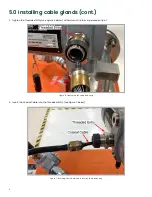
Page 9: ...mise the environmental ratings of the PanaFlow LZ system Note These instructions apply to all installations using the Panametrics 704 861 704 862 and 704 863 cable assemblies 1 Remove the Rubber Boot from the cable gland and slide it back over the cable see Figure 4 below Figure 4 Removing the rubber boot 2 Disassemble the Cable Gland see Figure 5 below However DO NOT try to separate the pieces of...

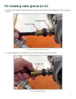
Page 10: ...e Threaded Entry see Figure 6 below with a wrench to form a permanent joint Figure 6 Tightening the threaded entry 4 Insert the Coaxial Cable into the Threaded Entry see Figure 7 below Figure 7 Inserting the coaxial cable into the threaded entry 6 ...

Page 11: ...d until the Armor Clamp is fully inserted into the Threaded Entry section see Figure 8 below Figure 8 Inserting the armor clamp into the gland 6 Screw the Middle Nut onto the cable gland to secure the clamped section see Figure 9 below Figure 9 Installing the middle nut 7 ...

Page 12: ...ely by hand see Figure 10 below Figure 10 Tightening the middle nut by hand 8 Tighten the Middle Nut with a wrench but be very careful not to overtighten the nut or the Armor Wires may be broken see Figure 11 below Figure 11 Tightening the middle nut with a wrench 8 ...

Page 13: ... over the Retaining Collar see Figure 12 below Figure 12 Screwing the back nut over the retaining collar 10 Hand tighten the Back Nut to secure the Coaxial Cable and make a weather tight seal see Figure 13 below Figure 13 Tightening the back nut by hand 9 ...

Page 14: ...d Assembly see Figure 14 below Figure 14 Sliding the rubber boot over the cable gland assembly 12 Make sure the Rubber Boot completely covers the Cable Gland and that no tears have occurred in the boot during the assembly process see Figure 15 below Figure 15 The Completed Cable Gland Assembly 10 ...

Page 15: ...used in this manual may appear slightly different from your system However the basic instructions are valid for all PanaFlow LZ systems a Connect the transducer wires to their terminal block per the instructions in the for your flow transmitter b Make sure all of the transducer wires are properly dressed and that they are neatly arranged inside the flow transmitter enclosure c Use the flexible str...

Page 16: ... s with a resolution of 2 mm s Accuracy statement assumes measurement of a single phase homogeneous liquid with a fully developed symmetrical flow profile passing through the meter Applications with piping arrangements that create an asymmetrical flow profile may require extended piping straight runs and or flow conditioning for the meter to perform to this specification Repeatability 0 3 of readi...

Page 17: ...n Electronics Transducers Explosion proof Class I Division 1 Groups B C D ATEX Flameproof II 2 G Ex d IIC T6 IECEx Flameproof II 2 G Ex d IIC T6 BWT only Flow Cell NACE MR0175 and MR0103 PED 2014 68 EU Dimensions Refer to drawings 712 2122 to 712 2125 Drawing Description 712 2122 General arrangement drawing PanaFlow LZ 6 and 3 1 path 2 traverse tilted diameter 712 2123 General arrangement drawing ...

Page 18: ... locations Armored flame retardant coaxial cables with ATEX IECEx certified cable glands for European hazardous locations Remote Cables ATEX IECEx Armored RG 62 for ATEX IECEx US CAN Non armored RG 62 conduit not included Remote cables are not included and must be ordered separately Maximum cable length is 1000 ft 300 m 14 ...

Page 19: ...15 ...

Page 20: ...n reduction targets across critical industries including Oil Gas Energy Healthcare Water and Wastewater Chemical Processing Food Beverage and many others Join the conversation and follow us on LinkedIn linkedin com company panametricscompany Copyright 2021 Baker Hughes Company All rights reserved 910 316 Rev A BHCS39032 07 2021 Customer support centers Europe Ireland Panametrics Shannon Free Zone ...

Reviews: