5. INSTALLATION AND WIRING
6
TECHNICAL DESCRIPTION 4318
• DOCUMENT NUMBER: MEW01961 • REVISION:
2
5
INSTALLATION AND WIRING
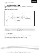
The detector is plugged in a base 2324. The zone line input and external LED are connected to the
base.
NOTE!
Screen wire termination is not provided.
DATA
2324
Wire size (Min)
Ø 0,65 mm (0,3 mm²)
Wire size (Max)
Ø 1,6 mm (2 mm²)
6
TEST MODE
For information about how to set a zone in test mode, see Planning Instructions or Operating
Instructions.
It is possible to use test equipment for testing, for example “SOLO” or “Testfire”.
External LED
c.i.e
Zon
e line
inp
ut
Mark
Mark
End-of-line device
Zone line


