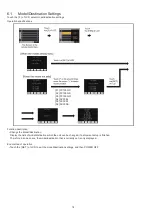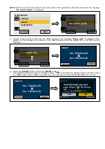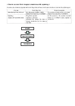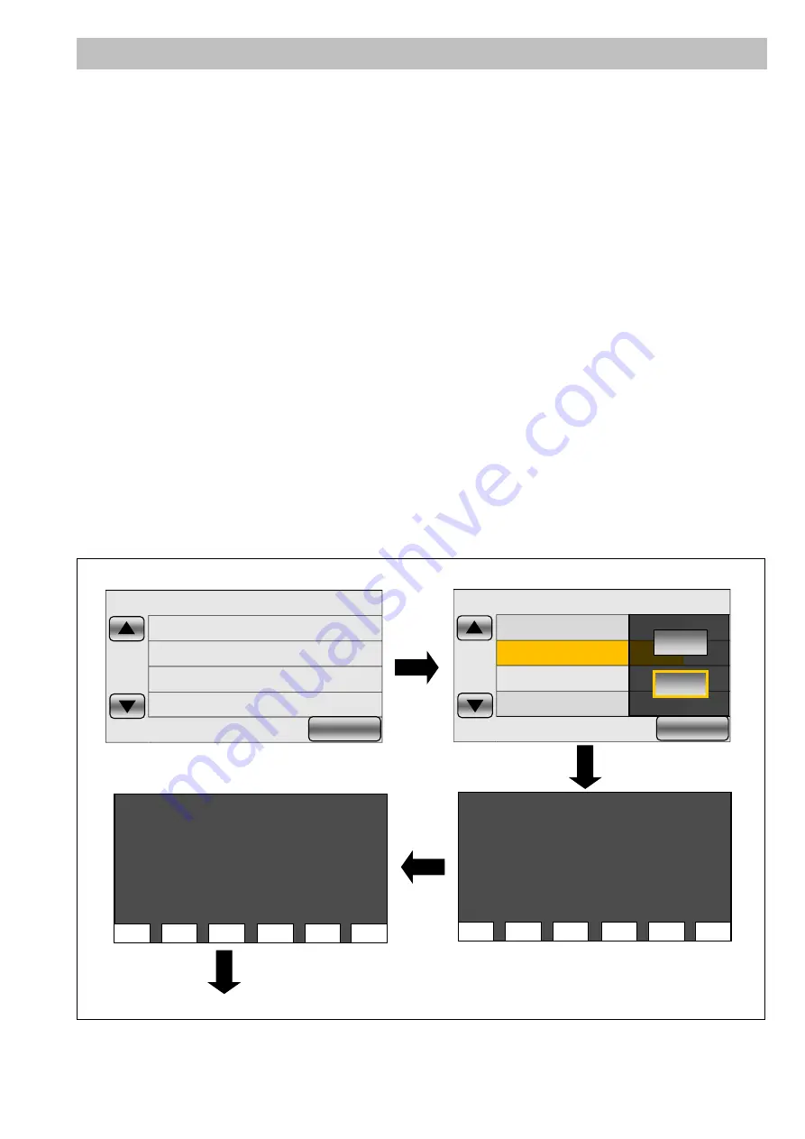
On the screen in the service mode “10”, Hour Meter or Error information that is displayed in the service mode “4” can
be reset.
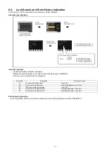
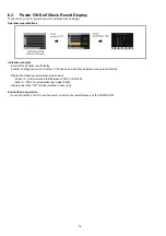
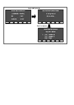
Touch “10” on the service mode menu screen.
YES/NO selection screen is displayed, then touch “YES” to display the HOUR METER RESET screen.
6-7. Hour Meter Reset
Top Screen of the service mode menu.
Touch the [10] of LCD.
Touch the [YES] of LCD.
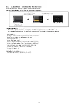
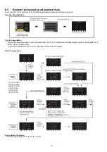
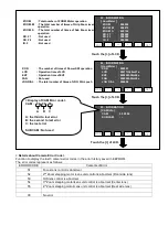
Select the reset item by touching [v], [^] of LCD.
ERROR&HOUR
ERROR INFO
HOUR METER
PWR
: All Hour Meter and Error Information reset
: All Error Information clear
: All Hour Meter reset
: Total power-on time reset
EE
SUB CAM
: Total EE-state (Recording mode) time
: Not used
REC SD1
: Total movie recording time (SD Slot1)
REC SD2
: Total movie recording time (SD Slot2)
INT SD1
: Total interval recording time (SD Slot1)
INT SD2
PICT SD1
PICT SD2
LAST PTH
SUM PTH
: Total interval recording time (SD Slot2)
: Total number of recorded still pictures (SD Slot1)
: Total number of recorded still pictures (SD Slot1)
: Not used
: Not used
1
NO
2
NO
4
NO
5
NO
EXIT
FF003014 001300 12 17C4 DCBA
AC30EJ(2.0) 50Hz SD(W)
Touch [SET] of LCD.
Touch the
▼
of LCD.
8
NO
10
NO
13
NO
14
NO
EXIT
FF003014 001300 12 17C4 DCBA
AC30EJ(2.0) 50Hz SD(W)
YES
NO
BAK
SET
>
<
^
V
>
[01] ERROR&HOUR
[02] ERROR INFO
[03] HOUR METER
HOUR METER RESET
SELECT MENU
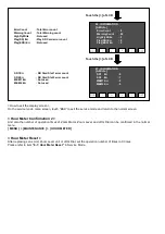
ZOOM
: Total number of ZOOM Motor operation
ZOOM. M
: The total number of times of Grip Zoom lever operation
ZOOM. S
FAN
P.ON
: The total number of times of Sub Zoom lever operation
: Not used
: The number of times of Power SW operation
ND. F1
: Not used
ND. F2
: Not used
IR. F
LCD
EVF
JOG DIAL
: Not used
: Operation time of LCD
: Operation time of EVF
: The total number of times of JOG DIAL push operation
BAK
SET
>
<
^
V
>
[16] ZOOM. M
[17] ZOOM. S
[18] FAN
HOUR METER RESET
SELECT MENU
Summary of Contents for AG-AC30PJ
Page 4: ...3 Model No AG AC30PJ PB ...
Page 5: ...4 ...
Page 6: ...5 ...
Page 7: ...6 ...
Page 8: ...7 Model No AG AC30EJ ...
Page 9: ...8 ...
Page 12: ...11 ...
Page 14: ......
Page 16: ...13 ...
Page 17: ...14 ...
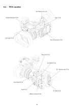
Page 37: ...24 8 2 PCB Location ...
Page 41: ...28 Fig D4 8 3 3 Removal of the Zoom Lever Unit Power SS Unit Grip Unit Fig D5 Fig D6 ...
Page 42: ...29 8 3 4 Removal of the Side Case L Unit Fig D7 Fig D8 ...
Page 43: ...30 8 3 5 Removal of the XLR Rear P C B Unit AV Jack P C B DC Remote Jack P C B Fig D9 Fig D10 ...
Page 44: ...31 Fig D11 8 3 6 Removal of the Sub Radiation Plate Unit Fig D12 ...
Page 45: ...32 8 3 7 Removal of the LED Light P C B Fig D13 8 3 8 Removal of the XLR Front Unit Fig D14 ...
Page 48: ...35 Fig D21 8 3 13 Removal of the Microphone Fig D22 ...
Page 49: ...36 8 3 14 Removal of the Handle Case L Unit Fig D23 8 3 15 Removal of the ND Case Fig D24 ...
Page 53: ...40 8 3 22 Removal of the Main P C B Fig D32 Fig D33 8 3 23 Removal of the Handle Unit Fig D34 ...
Page 55: ...42 Fig D39 8 3 26 Removal of the Battery Catcher P C B Fig D40 ...
Page 56: ...43 8 3 27 Removal of the Speaker Fig D41 8 3 28 Removal of the EVF Unit Fig D42 ...
Page 57: ...44 Fig D43 ...
Page 60: ...49 Level Shot Adjutment Chart ...
Page 62: ...51 9 1 2 Adjustment Items Adjustment item as follows ...
Page 65: ...54 ...
Page 66: ...55 ...
Page 67: ...56 ...
Page 68: ...57 ...
Page 69: ...58 ...
Page 70: ...59 ...
Page 71: ...60 ...
Page 72: ...61 ...
Page 85: ......
Page 86: ......
Page 116: ......
Page 119: ...1 5 2 6 R L 6 5 5 1 R L 6 5 5 2 F P 6 5 5 1 D 6 5 5 1 D 6 5 5 2 M K 1 M K 2 ...
Page 120: ......
Page 122: ...MK1 MK2 C3901 D3901 C3902 D3902 ...
Page 125: ...M K 3 M K 4 D 6 5 0 1 D 6 5 0 2 D 6 5 0 3 D 6 5 0 4 D 6 5 0 5 D 6 5 0 6 D 6 5 0 7 D 6 5 0 8 ...
Page 126: ...8 7 2 5 1 CL6501 CL6502 CL6503 RL6504 RL6505 FP6501 MK1 MK2 ...
Page 127: ...1 5 2 6 4 1 M K 1 M K 2 R L 6 9 3 6 F P 6 9 3 6 F P 6 9 3 7 ...
Page 128: ...1 ET6931 RL6937 ...
Page 131: ...1 4 2 3 M K 3 M K 4 J K 6 3 0 1 ...

