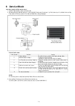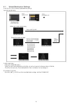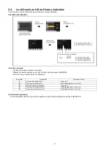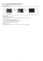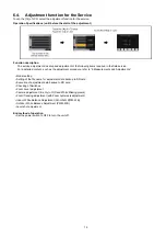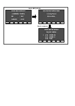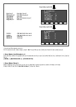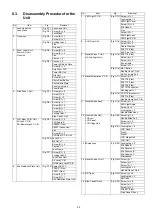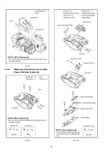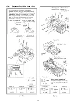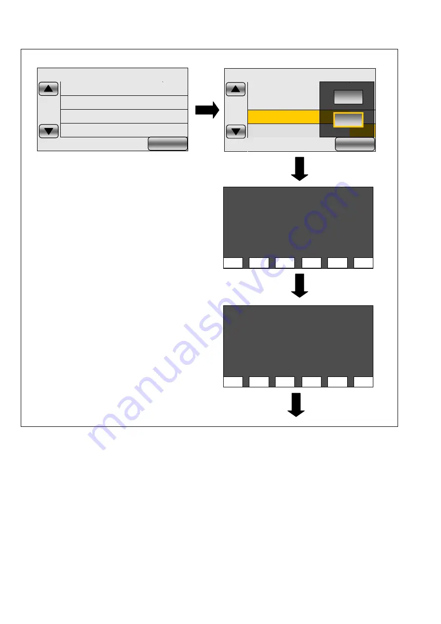
Touch “4” on the service mode menu screen.
YES/NO selection screen is displayed, then touch “YES” to display the INFORMATION screen.
1
NO
2
NO
4
NO
5
NO
EXIT
FF003014 001300 12 17C4 DCBA
AC30EJ(2.0) 50Hz SD(W)
YES
NO
Top Screen of the service mode menu.
Touch the [4] of LCD.
Touch the [YES] of LCD.
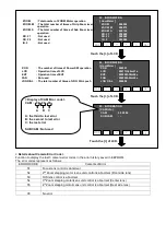
01 . INFORMATION
[ HourMeter ]
PWR
: 0010h37m17s
EE
: 0009h39m02s
REC SD1
: 0001h27m21s
REC SD2
: 0000h45m00s
INT SD1
: 0000h00m00s
INT SD2
: 0000h00m00s
BAK
SET
>
<
^
V
Touch the [>] of LCD.
PWR
: Total power-on time
EE
: Total EE-state (Recording mode) time
REC SD1
: Total movie recording time (SD Slot1)
REC SD2
: Total movie recording time (SD Slot2)
INT SD1
: Total interval recording time (SD Slot1)
INT SD2
: Total interval recording time (SD Slot2)
PICT SD1
: Total number of recorded still pictures
(SD Slot1)
PICT SD2
: Total number of recorded still pictures
(SD Slot2)
LAST PTH
: Not used
SUM PTH
: Not used
SUB CAM
: Not used
1
NO
2
NO
4
NO
5
NO
EXIT
FF003014 001300 12 17C4 DCBA
AC30EJ(2.0) 50Hz SD(W)
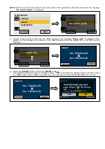
02 . INFORMATION
[ HourMeter ]
PICT SD1
: 000072
PICT SD2
: 000033
LAST PTH
: 000000h
SUM PTH : 000000h00m00s
SUB CAM : 000000h00m00s
BAK
SET
>
<
^
V
Touch the [>] of LCD.
Summary of Contents for AG-AC30PJ
Page 4: ...3 Model No AG AC30PJ PB ...
Page 5: ...4 ...
Page 6: ...5 ...
Page 7: ...6 ...
Page 8: ...7 Model No AG AC30EJ ...
Page 9: ...8 ...
Page 12: ...11 ...
Page 14: ......
Page 16: ...13 ...
Page 17: ...14 ...
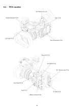
Page 37: ...24 8 2 PCB Location ...
Page 41: ...28 Fig D4 8 3 3 Removal of the Zoom Lever Unit Power SS Unit Grip Unit Fig D5 Fig D6 ...
Page 42: ...29 8 3 4 Removal of the Side Case L Unit Fig D7 Fig D8 ...
Page 43: ...30 8 3 5 Removal of the XLR Rear P C B Unit AV Jack P C B DC Remote Jack P C B Fig D9 Fig D10 ...
Page 44: ...31 Fig D11 8 3 6 Removal of the Sub Radiation Plate Unit Fig D12 ...
Page 45: ...32 8 3 7 Removal of the LED Light P C B Fig D13 8 3 8 Removal of the XLR Front Unit Fig D14 ...
Page 48: ...35 Fig D21 8 3 13 Removal of the Microphone Fig D22 ...
Page 49: ...36 8 3 14 Removal of the Handle Case L Unit Fig D23 8 3 15 Removal of the ND Case Fig D24 ...
Page 53: ...40 8 3 22 Removal of the Main P C B Fig D32 Fig D33 8 3 23 Removal of the Handle Unit Fig D34 ...
Page 55: ...42 Fig D39 8 3 26 Removal of the Battery Catcher P C B Fig D40 ...
Page 56: ...43 8 3 27 Removal of the Speaker Fig D41 8 3 28 Removal of the EVF Unit Fig D42 ...
Page 57: ...44 Fig D43 ...
Page 60: ...49 Level Shot Adjutment Chart ...
Page 62: ...51 9 1 2 Adjustment Items Adjustment item as follows ...
Page 65: ...54 ...
Page 66: ...55 ...
Page 67: ...56 ...
Page 68: ...57 ...
Page 69: ...58 ...
Page 70: ...59 ...
Page 71: ...60 ...
Page 72: ...61 ...
Page 85: ......
Page 86: ......
Page 116: ......
Page 119: ...1 5 2 6 R L 6 5 5 1 R L 6 5 5 2 F P 6 5 5 1 D 6 5 5 1 D 6 5 5 2 M K 1 M K 2 ...
Page 120: ......
Page 122: ...MK1 MK2 C3901 D3901 C3902 D3902 ...
Page 125: ...M K 3 M K 4 D 6 5 0 1 D 6 5 0 2 D 6 5 0 3 D 6 5 0 4 D 6 5 0 5 D 6 5 0 6 D 6 5 0 7 D 6 5 0 8 ...
Page 126: ...8 7 2 5 1 CL6501 CL6502 CL6503 RL6504 RL6505 FP6501 MK1 MK2 ...
Page 127: ...1 5 2 6 4 1 M K 1 M K 2 R L 6 9 3 6 F P 6 9 3 6 F P 6 9 3 7 ...
Page 128: ...1 ET6931 RL6937 ...
Page 131: ...1 4 2 3 M K 3 M K 4 J K 6 3 0 1 ...

