AV-HS450
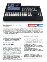
AV-HS410
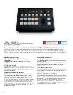
AW-HS50
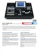
AG-HMX100
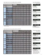
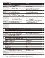
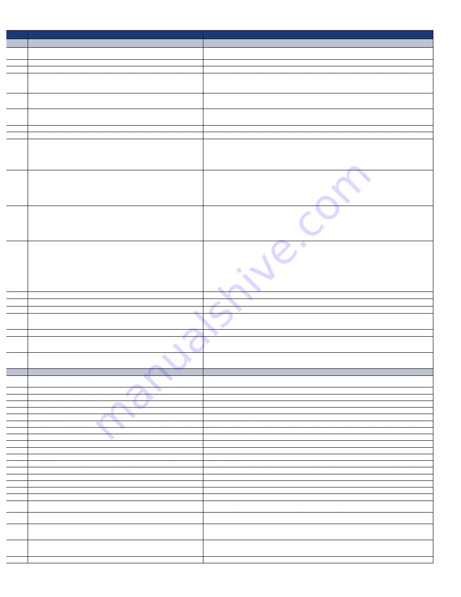
Specifications
Power Requirement
Mainframe:
AC 100 V to 120 V(N)/AC 220 V to 240 V(E), 50 Hz/60 Hz, 120 W
Control Panel: DC12 V ±10 % (AC adapter provided), 0.8 A
AC 100 V to 240 V, 50 Hz/60 Hz, 88 W
DC 12 V ±10 % (AC adapter provided), 2.0 A
AC 100 V to 240 V, 50 Hz/60 Hz, 60 W
Operating Temperature
0 °C to 40 °C (32 °F to 104 °F)
0 °C to 40 °C (32 °F to 104 °F)
0 °C to 40°C (32 °F to 104 °F)
5 °C to 40 °C (41 °F to 104 °F)
Operating Humidity
10 % to 90 % (no condensation)
10 % to 90 % (no condensation)
10 % to 90 % (no condensation)
10 % to 80 % (no condensation)
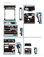
Dimensions (W x H x D)
Mainframe:
(2RU) 482 mm x 88 mm x 471 mm
(19 inches x 3-7/16 inches x 18-9/16 inches) (excluding protrusions)
Control Panel: 560 mm x 88 mm x 299 mm
(22-1/16 inches x 3-7/16 inches x 11-3/4 inches) (excluding protrusions)
440 mm x 158 mm x 361 mm
(17-5/16 inches x 6-7/32 inches x 14-7/32 inches) (excluding protrusions)
210 mm x 67 mm x 177 mm
(8-1/4 inches x 2-5/8 inches x 6-15/16 inches) (excluding protrusions)
424 mm x 197 mm x 400 mm
(16-3/4 inches x 7-3/4 inches x 15-3/4 inches) (excluding protrusions)
Weight
Mainframe:
Approx. 9.8 kg (21.6 lb) (without options/excluding accessories)
Approx. 10.3 kg (22.7 lb) (with full options/excluding accessories)
Control Panel: Approx. 3.9 kg (8.6 lb) (excluding accessories)
Approx. 6.2 kg (13.669 lb) (without options/excluding accessories)
Approx. 6.6 kg (14.550 lb) e (with full options/excluding accessories)
Approx. 1.4 kg (3.1 lb) (without options)
Approx. 7.9 kg (17.4 lbs) (without options)
Video Format
HD:
1080/59.94i, 1080/50i, 1080/24PsF*
1
, 1080/23.98PsF*
1
,
720/59.94p, 720/50p
SD:
480/59.94i, 576/50i
HD:
1080/59.94i, 1080/50i, 1080/24PsF*
2
, 1080/23.98PsF*
2
,
720/59.94p, 720/50p,
SD:
480/59.94i, 576/50i
HD:
1080/59.94i, 1080/50i, 1080/24PsF, 1080/23.98PsF, 720/59.94p, 720/50p
SD:
480/59.94i, 576/50i
HD:
1080/23.98PsF (for 3D only), 1080/59.94i, 1080/50i, 720/59.94p, 720/50p
SD:
480/59.94i, 576/50i
*Mixed operation of different video formats is not possible.
Video Processing
Y:C
B
:C
R
4:2:2, 10 bit (8 bit for FMEM) /RGB 4:4:4, 8 bit
Y:C
B
:C
R
4:2:2, 10 bit (8 bit for video memory) /RGB 4:4:4, 8 bit
Y:C
B
:C
R
4:2:2, 10 bit (8 bit for FMEM)/ RGB 4:4:4, 8 bit
Y:P
B
:P
R
:Key 4:2:2:4, 12 bit (Internal process)
ME
1ME
1ME
1ME
1ME
Video Input*
3
Mainframe, A maximum of 20 inputs
Standard SDI: 16 lines, BNC x 16 (IN 1 to 16)
HD (SMPTE292M)/SD (SMPTE259M) standard, 0.8 V [p-p] ±10 % (75 Ω)
Optional:
Maximum of 4 inputs (IN A1, A2, B1, B2)(Up to 2 optional boards
may be inserted into the 2 input/output optional slots)
A maximum of 13 inputs
Standard SDI: 8 lines, BNC x 8 (IN 1 to 8) (Up-convert support with IN 5 to 8)
HD (SMPTE292M)/SD (SMPTE259M) standard, 0.8 V [p-p] ±10 % (75 Ω)
Standard DVI-D: 1 line, DVI-D x 1 (Analog input signals are not supported)
Optional:
Maximum of 4 inputs (IN A1, A2, B1, B2) (Up to 2 optional
boards may be inserted into the 2 input/output optional slots)
SDI:
4 lines, BNC x 4
HD (SMPTE292M)/SD (SMPTE259M) standard
0.8 V [p-p] ±10 % (75 Ω)
DVI-D:
1 signal line, DVI-D x 1 (Analog input signals are not supported)
VIDEO:
2 lines, BNC x 2, Analog Composite, 1.0 V[p-p] (75 Ω)
SDI:
4 lines, BNC x 4
HD (SMPTE292M/296M/299M) /SD (SMPTE259M-C/272M-A, ITU-R. BT.656-4) standard
HDMI:
2 signal lines, HDMI x 2 (Type A connector), incompatible with HDCP Link and VIERA Link
DVI-I:
TMDS single link (incompatible with HDCP), compatible with digital/analog RGB
Video Output*
3
Mainframe, A maximum of 10 outputs
Standard SDI: 4 lines, BNC x 5 (OUT 1 to 4 x each, 2 output distribution for OUT 1)
HD (SMPTE292M)/SD (SMPTE259M) standard, 0.8 V [p-p] ±10 % (75 Ω)
Standard DVI-D: 2 lines, DVI-D x 2, (OUT 5, 6)
(Analog output signals are not supported)
Optional:
Maximum of 12 outputs (OUT A1, A2, B1, B2) (Up to 2 optional boards
may be inserted into the 2 input/output optional slots)
A maximum of 10 outputs
Standard SDI: 5 lines, BNC x 6 (OUT 1 to 5 x each, 2 output distribution for OUT 1)
HD (SMPTE292M)/SD (SMPTE259M) standard, 0.8 V [p-p] ±10 % (75 Ω)
Standard DVI-D: 1 line, DVI-D x 1 (Analog output signals are not supported)
Optional:
Maximum of 4 outputs (OUT A1, A2, B1, B2)
(Up to 2 optional boards may be inserted into the 2 input/
output optional slots)
SDI:
2 lines, BNC x 3 (2 output distribution for OUT1)
HD (SMPTE292M)/SD (SMPTE259M) standard
0.8 V [p-p] ±10 % (75 Ω)
DVI-D:
1 signal line, DVI-D x 1 (Analog output signals are not supported.)
SDI:
4 lines, BNC x 4 (PGM/PVW/AUX/MULTIVIEW x each)
HD (SMPTE292M/296M/299M) /SD (SMPTE259M-C/272M-A, ITU-R. BT.656-4) standard
DVI-D:
2 lines, DVI-D x 2 (PGM/MULTIVIEW x each)
TMDS single link (not compatible with HDCP)
Reference Input/Output
Mainframe
GENLOCK mode:
Black burst or Tri-level Sync input signals (with loop-through)
Internal sync mode: Black burst output signals x 2
• Same field frequencies as those of the system formats supported.
• With the 1080/23.98PsF, 1080/24PsF format, only GENLOCK mode supported.
• With the 1080/23.98PsF format, black burst with 10F-ID
(SMPTE318M standard met) or TRI signals supported.
GENLOCK mode:
Black burst or Tri-level Sync input signals (with loop-through)
Internal sync mode: Black burst output signals x 2
• Same field frequencies as those of the system formats supported.
• With the 1080/24PsF format, only GENLOCK mode supported.
• With the 1080/23.98PsF format, black burst with 10F-ID
(SMPTE318M standard met) or TRI signals supported.
—
External reference (G/L) input:
BNC x 2 (with loop-through), 1.0 V [p-p] (75 Ω), Analog composite (NTSC/PAL)
Advanced reference (ADV-REF) output:
BNC x 1, 75 Ω, Analog composite
Sync: 0.286 V [p-p] (NTSC)/0.3 V [p-p] (PAL)
Burst: 0.286 V [p-p] (NTSC)/0.3 V [p-p] (PAL)
Audio Input/Output
—
—
—
AUDIO input:
XLR: 4 lines (L and R), +4/0/–3 dBm switchable, balanced, 600 Ω
SDI (embedded audio): 4 lines, HD (SMPTE292M/296M/299M)/SD (SMPTE259M-C/272M-A, ITU-R BT.656-4) standard
HDMI (embedded audio): 2 lines, Type A connector (not compatible with HDCP)
AUX input:
Pin jack: 1 line (L and R),–10 dBV, High impedance, unbalanced
MIC input:
M6 x 1 line, –60 dBV, 2 kΩ, monaural, unbalanced
AUDIO output: PGM: XLR: 1 line (L and R), +4/0/–3 dBm switchable, Low impedance, balanced
Pin jack: 1 line (L and R), –10 dBV, Low impedance, unbalanced
PGM/PVW/AUX OUT: SDI (Embedded Audio) x 1,
HD (SMPTE292M/296M/299M)/SD (SMPTE259M-C/272M-A, ITU-R BT.656-4) standard
PHONES output: M6 x 1, 8 Ω, stereo, unbalanced, –∞ dBu to –20 dBu
Interface
PANEL/MAINFRAME RJ45 x 1, 100 Mbps (to connect between the mainframe and the control panel)
—
—
—
EDITOR
Mainframe, D-sub 9 pin x 1, RS-422 (GVG protocol compatible)
DD-sub 9 pin x 1, RS-422
—
—
COM
Mainframe, D-sub 9 pin x 1, RS-422 (pan-tilt system control)
D-sub 9 pin x 1, RS-422
—
D-sub 9 pin x 1, RS-232C
TALLY/GPI
Mainframe:
D-sub 50 pin x 1 (8 IN, 31 OUT and 1 ALARN OUT may be set)
Control Panel: D-sub 25 pin x 1 (8 IN and 8 OUT may be set)
D-sub15 pin x 2 (IN 8, OUT 19, ALARM OUT 1)
D-sub 15 pin x 1, GPI INPUT x 5 channels (photocoupler sensing),
GPI OUTPUT x 7 channels (open collector output)
TALLY output: D-sub 9 pin x 1, 8 Cross point, Open-collector, Maximum current: Less than 50 mA,
Maximum Voltage: 35 VDC
GPI:
BNC x 1, Make-Contact
LAN
Mainframe, RJ45 x 1, 10 BASE-T/100 BASE-TX
RJ45, 10 BASE-T/100 BASE-TX
RJ45, 10 BASE-T/100 BASE-TX
—
Removable
Media
SD Memory Card
Supported by the control panel,
Capacity:
Maximum 32 GB (SDHC Memory Card compatible)
Still image file: Loading/saving, setup data: backup
Capacity:
Maximum 32 GB (SDHC Memory Card compatible)
Still image file/movie clip file/shot memory/event memory: Loading/saving,
Setup data: backup
—
—
Standard Accessories
CD-ROM (Operating instructions / Image transmission software),
AC adapter (for control panel),Power cable (for mainframe and AC adapter),
CAT5E cable (STP, straight cable, 10 m (32.8 feet) long)
CD-ROM (Operating instructions/DVI input level adjustment file),
Power cable (2 m (6.6 feet) long)
CD-ROM (Operating instructions / Image transmission software), AC adapter
CD-ROM (Operating instructions), Power code (3 core cable)
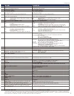
Function
BKGD
Wipe/DVE Pattern
Wipe x 12, Squeeze x 11, Slide x 8, 3D x 12, 2ch squeeze x 4, 2ch slide x 4, 2ch 3D x 4
Wipe x 16, Squeeze x 16, Slide x 8, 3D x 12
Wipe x 13
Wipe (2) x 37, Wipe (+MULTI) x 16, Wipe (BLIND) x 23, Wipe (MATRIX) x 7,
Squeeze (COMP+SINGLE) x 13, 2ch Squeeze (COMP+BOTH) x 8, Slide x 8
Transition Type
Cut, Mix, Wipe (including DVE)
Cut, Mix, Wipe (including DVE)
Cut, Mix, Wipe
Cut, Mix, Wipe (including DVE)
Image
Image effect: PGM/A, PST/B BUS Effect: Mosaic, Defocus, Mono, Paint
—
—
Image effect: PGM/A, PST/B BUS Effect: Mosaic, Defocus, Mono, Time effects, Decay, Paint, Nega, Mirror
KEYER
Number of Keys
1
1
1
1
Key Type
Linear key, Luminance key, Chroma key, Full key
Linear key, Luminance key, Chroma key, Full key*
8
Linear key, Luminance key, Chroma key*
8
Linear key, Luminance key, Chroma key, Full key
Transition Type
Cut, Mix, Wipe (including DVE)
Cut, Mix, Wipe (including DVE)
Mix
Cut, Mix, Wipe (including DVE)
Wipe/DVE Pattern
Wipe x 12, Squeeze x 11, Slide x 9, 3D x 12
Wipe x 16, Squeeze x 16, Slide x 8, 3D x 12
—
Wipe x 6
DSK
Number of Keys
2
1
—
1
Key Type
Linear key, Luminance key
Linear key, Luminance key
—
Luminance key
Transition Type
Mix
Mix
—
Mix
P in P
Number of PinP
2
2
1
1
Transition Type
Mix
Mix
Mix
Mix
AUX BUS
AUX Bus 1 to 4*
4
AUX Bus 1 to 4*
4
AUX BUS1
—
Input
Function
Frame Synchronizer
IN 1 to 16*
5
IN 1 to 9 (IN 9 is always-on)*
5
SDI-IN 1 to 4, DVI-IN (always-on)
SDI-IN 1 to 4, DVI-I IN, HDMI 1 to 2/Composite video 1 to 2
Freeze
IN 1 to 16*
5
IN 1 to 9*
5
SDI-IN1 to 4, DVI-IN
SDI-IN 1 to 4, DVI-I IN, HDMI 1 to 2/Composite video 1 to 2
Up-Converter
IN13 to 16*
5
IN5 to 8*
5
SDI-IN3, 4
—
Color Corrector
IN9 to 16
—
—
—
Video Processing
—
IN1 to 8*
5
SDI-IN 1 to 4
Every A/B bus
Output
Function
MultiViewer
2 systems, Labels, Tally indication, Split-screen
(the screen may be split into 4, 9, 10 and 16 sections)*
6
1 system, Labels, Tally indication, Split-screen (9 Patterns: 4, 5a/5b, 6a/6b, 9, 10a/10b
and 16 sections)
1 system*
10
, Labels, Tally indication, Split-screen (8 Patterns: 4, 5a/5b, 6a/6b, 9 and
10a/10b sections)
1 system
Labels, Tally indication, Split-screen (the screen split into 10a only)
Other Function
OSD (PVW and several MULTI outputs), Phase adjustment,
Chroma key sample marker, Down converter (SDI output board only)
Phase adjustment, Chroma key sample marker,
Down converter (SDI output board only)
OSD [Single Screen Display: SDI-OUT 2,DVI-OUT (unshown on SDI-OUT 1)],
Chroma key sample marker, Audio Level Meter: SDI embedded audio (group1/ 1 ch, 2 ch) OSD (several MULTI outputs), WFM, Audio level meter, Embedded audio(SDI, HDMI)
Frame Memory
4 channels (The data for the images stored in the frame memories can be retained even
when the power is turned off by saving it in the flash memory area which is incorporated
inside the unit.)
—
2 channels *
11
(The data for the images stored in the frame memories can be retained
even when the power is turned off by saving it in the flash memory area which is
incorporated inside the unit.)
1 systems: still images and movie clips
Video Memory
—
2 systems: still images and movie clips (The data for the images stored in the frame
memories can be retained even when the power is turned off by saving it in the flash
memory*
9
area which is incorporated inside the unit.)
—
—
Memory Function
Shot memory, BKGD/Wipe memory, PinP memory, Camera memory *
7
, Effect dissolve function Shot memory, Event memory, Effect dissolve function
PinP Preset, Effect dissolve function
Event memory (100 patterns), Key learning (20 patterns)
(As of April, 2012)
*7: May store and recall up to 10 presets (per camera) with current Panasonic pan-tilt systems. *8: May also be used for DSK applications by changing the key layer. *9: Plans call for supporting this
function in the future. *10: OSD, MV frames, Labels, Tally indications, Audio Level Meters, and Camera setting information are not shown on SDI-OUT 1. *11: OSD, MV frames, Labels, Tally indications,
Audio Level Meters, and Camera setting information for MultiViewer Display are not stored in the Frame Memory.
18


