background image

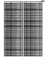
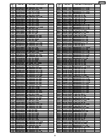
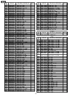
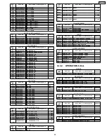
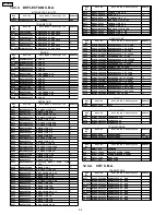
Ref.

No.

Part No.

Part Name & Description

Remarks

R6213

ERJ3GEYJ101V

MGF CHIP 1/16W 100

R6214

ERJ3GEYJ473V

MGF CHIP 1/16W 47K

R6301

ERJ3EKF2201V

MGF CHIP 1/16W 2.2

R6302

ERJ3EKF3301V

MGF CHIP 1/16W 3.3K

R6303

ERJ3EKF5601V

MGF CHIP 1/16W 5.6K

R6304

ERJ3EKF1102V

MGF CHIP 1/16W 11K

R6306

ERJ3EKF2201V

MGF CHIP 1/16W 2.2

R6307

ERJ3EKF3301V

MGF CHIP 1/16W 3.3K

R6308

ERJ3EKF5601V

MGF CHIP 1/16W 5.6K

R6309

ERJ3EKF1102V

MGF CHIP 1/16W 11K

R6311

ERJ3EKF2201V

MGF CHIP 1/16W 2.2

R6312

ERJ3EKF3301V

MGF CHIP 1/16W 3.3K

R6316

ERJ3EKF1102V

MGF CHIP 1/16W 11K

R6317

ERJ3EKF1102V

MGF CHIP 1/16W 11K

R6318

ERJ3EKF1102V

MGF CHIP 1/16W 11K

R6321

ERJ3GEYJ103V

MGF CHIP 1/16W 10K

R6322

ERJ3GEYJ103V

MGF CHIP 1/16W 10K

R6323

ERJ3GEYJ103V

MGF CHIP 1/16W 10K

R6401

ERJ3GEYJ105V

MGF CHIP 1/16W 1M

R6511

ERJ3GEYJ472V

MGF CHIP 1/16W 4.7K

R6512

ERJ3GEYJ472V

MGF CHIP 1/16W 4.7K

R6513

ERJ3GEYJ222V

MGF CHIP 1/16W 2.2K

R6514

ERJ3GEYJ472V

MGF CHIP 1/16W 4.7K

R6515

ERJ3GEYJ222V

MGF CHIP 1/16W 2.2K

R6516

ERJ3GEYJ101V

MGF CHIP 1/16W 100

R6517

ERJ3GEYJ223V

MGF CHIP 1/16W 22K

R6522

ERJ3GEY0R00V

MGF CHIP 1/16W 0

R7001

ERJ3GEYJ102V

MGF CHIP 1/16W 1K

R7002

ERJ3GEYJ101V

MGF CHIP 1/16W 100

R7003

ERJ3GEYJ101V

MGF CHIP 1/16W 100

R7033

ERJ3GEYJ102V

MGF CHIP 1/16W 1K

R9501

ERJ3GEYJ750V

MGF CHIP 1/16W 75

R9502

ERJ3GEY0R00V

MGF CHIP 1/16W 0

R9503

ERJ3GEY0R00V

MGF CHIP 1/16W 0

R9509

ERJ3GEYJ102V

MGF CHIP 1/16W 1K

R9510

ERJ3GEYJ102V

MGF CHIP 1/16W 1K

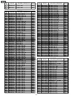
CAPACITORS

Ref.

No.

Part No.

Part Name & Description

Remarks

C801

F0CAF334A021

POLYESTER 125V 0.33UF

C803

F0CAF104A021

POLYESTER 125V 0.1UF

C804

ECKATS102ME

CERAMIC 250V 1000PF

or C804 ECKETS102ME

CERAMIC 250V 1000PF

or C804 F1BAF102A059

CERAMIC 250V 1000PF

or C804 F1BAH1020011

CERAMIC 250V 1000PF

or C804 F1BAH1020013

CERAMIC 250V 1000PF

or C804 F1B2E1020004

CERAMIC 250V 1000PF

C806

F1BAF472A082

CERAMIC 250V 4700PF

C807

F1BAF472A082

CERAMIC 250V 4700PF

C808

F1BAF472A082

CERAMIC 250V 4700PF

C809

F1BAF472A082

CERAMIC 250V 4700PF

C855

ECA1HHG470B

ELECTROLYTIC 50V 47UF

C856

ECJ1VB1H471K

C CHIP 50V 470PF

C857

F2B2D3310020

ELECTROLYTIC 200V 330UF

C858

F1B3D152A010

CERAMIC 2KV 1500PF

C859

F1H1H221A009

C CHIP 50V 220PF

C861

ECKATS152ME

CERAMIC 250V 1500PF

or C861 ECKETS152ME

CERAMIC 250V 1500PF

C864

ECKR3A102KBP

CERAMIC 1KV 1000PF

C865

F2A1E4710047

ELECTROLYTIC 25V 470UF

C867

F2B2D3310020

ELECTROLYTIC 200V 330UF

C868

F2A1E4710047

ELECTROLYTIC 25V 470UF

C869

ECKN3A221KBP

CERAMIC 1KV 220PF

C870

F2A2D4R70010

ELECTROLYTIC 200V 4.7UF

C872

F2A2D8200003

ELECTROLYTIC 200V 82UF

C1001

ECKATS332ME8

CERAMIC 250V 3300PF

or
C1001

ECKETS332ME8

CERAMIC 125V 3300PF

or
C1001

F1BAF3320029

CERAMIC 250V 3300PF

C1003

ECA1HHG470I

ELECTROLYTIC 50V 47UF

C1004

ECKATS102ME

CERAMIC 250V 1000PF

C1005

F2A2D8200003

ELECTROLYTIC 200V 82UF

Ref.

No.

Part No.

Part Name & Description

Remarks

C1006

ECJ1VB1H471K

C CHIP 50V 470PF

C1007

F1B3D681A011

CERAMIC 2KV 680PF

C1008

ECA1HHG010B

ELECTROLYTIC 50V 1UF

C1010

F1J1H1040003

C CHIP 50V 0.1UF

C1011

ECA1HHG470B

ELECTROLYTIC 50V 47UF

C1013

ECA1HHG470B

ELECTROLYTIC 50V 47UF

C1015

F1H1H102A219

C CHIP 50V 1000PF

C1016

F1H1H103A220

C CHIP 50V 0.01UF

C1017

ECA1HHG470B

ELECTROLYTIC 50V 47UF

C1018

F1J1H101A411

C CHIP 50V 100PF

C1020

F2A1E4710070

ELECTROLYTIC 25V 470UF

C1021

F1J1C2240007

C CHIP 16V 0.22UF

C1024

F2A1E3310040

ELECTROLYTIC 25V 330UF

C1025

F2A1E3310040

ELECTROLYTIC 25V 330UF

C1026

EEUFF0J222E

ELECTROLYTIC 6.3V 2200UF

C1027

ECA1HHG470B

ELECTROLYTIC 50V 47UF

C1028

F2A1E3310040

ELECTROLYTIC 25V 330UF

C1029

F2A1E3310040

ELECTROLYTIC 25V 330UF

C1030

F2A1E3310040

ELECTROLYTIC 25V 330UF

C1031

EEUFF0J222E

ELECTROLYTIC 6.3V 2200UF

C1033

ECA1HHG470I

ELECTROLYTIC 50V 47UF

C1034

F2A0J331A137

ELECTROLYTIC 6.3V 330UF

C1035

F1H1A105A028

C CHIP 10V 1UF

C1036

F1H1A105A028

C CHIP 10V 1UF

C1037

F2A1E3310040

ELECTROLYTIC 25V 330UF

C1038

EEUFF0J222E

ELECTROLYTIC 6.3V 2200UF

C1040

F2A1E3310040

ELECTROLYTIC 25V 330UF

C1203

ECA1HHG100I

ELECTROLYTIC 50V 10UF

C1204

ECA1HHG470I

ELECTROLYTIC 50V 47UF

C1210

F2A1C2200034

ELECTROLYTIC 16V 22UF

C1212

ECEA0JEE101

ELECTROLYTIC 6.3V 100UF

C1213

F2A1E3310040

ELECTROLYTIC 25V 330UF

C1214

ECA1HHG470I

ELECTROLYTIC 50V 47UF

C1218

ECA1HHG470B

ELECTROLYTIC 50V 47UF

C1301

F1J1C474A091

C CHIP 16V 0.47UF

C1302

F1H1A105A028

C CHIP 10V 1UF

C1603

F2A1E4R70022

ELECTROLYTIC 25V 4.7UF

C1621

F1H1H270A736

C CHIP 50V 27PF

C1622

F1H1C104A041

C CHIP 16V 0.1UF

C3001

F2A1C1000035

ELECTROLYTIC 16V 10UF

C3002

F1H1C104A041

C CHIP 16V 0.1UF

C3003

F1H1C104A041

C CHIP 16V 0.1UF

C3004

F1H1H151A737

C CHIP 50V 150PF

C3005

F1H1C104A041

C CHIP 16V 0.1UF

C3006

F1H1C104A041

C CHIP 16V 0.1UF

C3007

ECJ1VC1H330J

C CHIP 50V 33PF

C3008

F2A1H4R70022

ELECTROLYTIC 50V 4.7UF

C3009

F1H1A105A028

C CHIP 10V 1UF

C3010

F1H1A105A028

C CHIP 10V 1UF

C3011

F1H1A105A028

C CHIP 10V 1UF

C3012

F1H1C104A041

C CHIP 16V 0.1UF

C3013

F1H1A224A012

C CHIP 10V 0.22UF

C3014

F2A0J4700014

ELECTROLYTIC 6.3V 47UF

C3015

F1H1C104A041

C CHIP 16V 0.1UF

C3016

F1H1A105A028

C CHIP 10V 1UF

C3017

F1H1C104A041

C CHIP 16V 0.1UF

C3018

F1H1C104A041

C CHIP 16V 0.1UF

C3019

F1H1C104A041

C CHIP 16V 0.1UF

C3020

F2A1H3R30014

ELECTROLYTIC 50V 3.3UF

C3021

F1H1H103A219

C CHIP 50V 0.01UF

C3022

F1H1H103A220

C CHIP 50V 0.01UF

C3023

F2A1C1000035

ELECTROLYTIC 16V 10UF

C3024

F1H1H3310001

C CHIP 50V 330PF

C3025

F2A0J4700014

ELECTROLYTIC 6.3V 47UF

C3026

F1H1H103A219

C CHIP 50V 0.01UF

C3028

F1H1H103A220

C CHIP 50V 0.01UF

C3029

F1H1H103A220

C CHIP 50V 0.01UF

C3030

F1H1A105A028

C CHIP 10V 1UF

C3031

F1H1H2R00008

C CHIP 50V 2PF

C3032

F2A0J4700014

ELECTROLYTIC 6.3V 47UF

C3033

F1H1A224A012

C CHIP 10V 0.22UF

C3034

F1H1C104A041

C CHIP 16V 0.1UF

C3035

F2A1H3R30014

ELECTROLYTIC 50V 3.3UF

92

AG-520VDH

Summary of Contents for AG520VDH - COMB. DVD/VCR/TV

Page 1: ...d Unauthorized copying and distribution is a violation of law AG 520VDH TV DVD VCR Combination For servicing the R4 Mechanism Chassis for PV Model Please refer to the R4 Mechanism Chassis for PV Model Service Manual Order No MKE0401000C1 ORDER NO MKE0507602CE D1 ...

Page 2: ...27 7 3 ELECTRICAL ADJUSTMENT 28 7 4 TEST POINTS AND CONTROL LOCATION 35 8 SCHEMATIC DIAGRAMS 37 8 1 SCHEMATIC DIAGRAM AND CIRCUIT BOARD LAYOUT NOTES 37 8 2 MAIN SCHEMATIC DIAGRAMS 38 8 3 DEFLECTION SCHEMATIC DIAGRAM 48 8 4 OPERATION CRT SCHEMATIC DIAGRAMS 49 8 5 DVD MAIN DVD SUB SCHEMATIC DIAGRAMS 50 8 6 INTERCONNECTION SCHEMATIC DIAGRAM 55 8 7 VOLTAGE CHART 56 9 CIRCUIT BOARD LAYOUT 61 9 1 MAIN C...

Page 3: ...eration Operation of the TV set without the rear cover involves the danger of a shock hazard from the TV set power supply Servicing should not be attempted by anyone who is not thoroughly familiar with the precautions necessary when working on high voltage equipment Always discharge the anode of the picture tube to the CRT ground of receiver before handling the tube 8 After servicing make the foll...

Page 4: ...cur it means that X ray protect circuit is not operating Further confirmation and repair is required 2 2 REPAIR PROCEDURES OF HORIZONTAL OSCILLATOR DISABLE CIRCUIT 1 Connect a DC voltmeter between capacitor C513 on the Main circuit board and chassis ground 2 If approximately 21 5 V For model with 20 inch CRT 20 0 V For model with 27 inch CRT is not present at that point when 120 V AC is applied fi...

Page 5: ... opening door or the other openings to look into the interior unit LASER Specification Class I level A LASER Product Class 1 level A LASER Product Wave Length 640 677 nm at DVD 770 810 nm at CD Laser Power No hazardous radiation is emitted with the safety protection 2 5 PRECAUTION OF LASER DIODE CAUTION This unit utilizes a class III a laser Visible laser radiation is emitted from the optical pick...

Page 6: ...as anti static ESD protected can generate electrical charge sufficient to damage ES devices 5 Do not use freon propelled chemicals These can generate electrical charges sufficient to damage ES devices 6 Do not remove a replacement ES device from its protective package until immediately before you are ready to install it Most replacement ES devices are packaged with leads electrically shorted toget...

Page 7: ...4 ABOUT LEAD FREE SOLDER PbF 7 AG 520VDH ...

Page 8: ...ayed and then the POWER button is pressed back on 1 With power turned off press FF and REW buttons on the unit together for over 3 seconds Fig 1 1 2 TV power comes on and the unit goes into service mode The following codes will be displayed Fig 1 2 Fig 1 3 Note Press any operation button except for POWER or PLAY DVD on either the unit or DVD key on the remote to detecet that a key has been pressed...

Page 9: ...Fig 1 6 9 AG 520VDH ...

Page 10: ...lay time in hours will be cleared to 0 3 To release from Usage Screen Mode press any operation button on VCR or insert a cassette tape in this mode VCR will return to normal operation mode 5 1 3 GROUNDING FOR ELECTROSTATIC BREAKDOWN Prevention 1 Human body grounding Use the antistatic wrist strap to discharge the static electricity from your body 2 Work table grounding Put a conductive material sh...

Page 11: ...2 4 Press the LEFT or RIGHT key on the remote again to enter DVD Service Mode II Fig 5 3 Note a After replacing the DVD Unit press the CLEAR key on the remote in this mode The total elapsed Disc Motor on time in hours minutes will be cleared to 0 b If 01 or 02 is always displayed in 9 DM STATUS replace the DVD Unit because the Disc Motor is defective 5 To confirm the value of JITTER and the value ...

Page 12: ...odels To obtain these Service Positions the 2 Extension Cables 13P LSUA0047 and 16P LSUA0048 are necessary 5 1 6 1 1 Service Position 1 1 Remove the Rear Cover Then pull the VCR DVD Ass y out and place it upright Fig 6 1 5 1 6 1 2 Service Position 2 1 Remove the Rear Cover Then turn the VCR DVD Ass y to the right 2 Connect the DVD Main C B A using the Extension Cable 16P Fig 6 2 5 1 6 1 3 Service ...

Page 13: ...ress and hold STOP EJECT PLAY and CH DOWN buttons on the unit together over 5 seconds in power on condition The unit goes into Service Mode Fig 7 1 To release from this mode disconnect AC Plug 5 1 9 MECHA MANUAL MODE In shut off condition or in Service Mode press the CH UP on the unit and CH UP buttons on the remote together without a cassette In this mode Loading or Unloading operation can be con...

Page 14: ...ce the instrument in the STOP mode and place a jumper between TP6003 and TP6009 on the Main C B A The tracking will be placed in the neutral position 5 1 12 CAUTION FOR INSTALLATION OF VCR DVD ASS Y CAUTION Opener Lever may be damaged when VCR DVD Ass y is installed with Cassette Door Lid and Opener Lever of Cassette Up Ass y set incorrectly Install the VCR DVD Ass y as follows 1 Swing the Cassett...

Page 15: ...the Mechanism and the Main C B A Be careful with the direction of F F C s to connectors as shown Fig 10 5 1 13 2 F F C between the DVD Unit DVD Main C B A and the Main C B A Be careful with the direction of F F C to connector as shown Fig 11 15 AG 520VDH ...

Page 16: ...5 1 14 WIRE AND LEAD POSITION DIAGRAM Fig 12 16 AG 520VDH ...

Page 17: ...3 Playback a recording of P B S channel including clock set data and confirm this feature 5 1 19 VARIABLE VOLTAGE ISOLATION TRANSFORMER An Isolation Transformer should always be used during the servicing of Combination DVD VCR whose chassis is not isolated from the AC power line Use a transformer of adequate power rating as this protects the technician from accidents resulting in personal injury f...

Page 18: ...5 2 MAINTENANCE CHART 18 AG 520VDH ...

Page 19: ...y Flowchart shown below When reassembling use the reverse procedure CAUTION 1 Disconnect AC plug before disassembly 2 Before connecting the AC plug be sure to confirm the connection between the Connector P502 on the Deflection C B A and P851 P852 on the Main C B A Otherwise some electrical parts may be damaged due to a sudden power surge Fig D1 19 AG 520VDH ...

Page 20: ...Fig D2 20 AG 520VDH ...

Page 21: ...Fig D3 21 AG 520VDH ...

Page 22: ...Fig D4 22 AG 520VDH ...

Page 23: ... Ass y is installed with Cassette Door Lid and Opener Lever of Cassette Up Ass y set incorrectly a When installing the VCR DVD Ass y swing the Cassette Door Lid all the way open until the Cassette Door tab clears the Opener Lever b Make sure that all guide tabs are aligned properly Then press the VCR DVD Ass y straight in 23 AG 520VDH ...

Page 24: ...tion of DVD Main C B A and DVD Sub C B A a Confirm that the Lever A is positioned as shown and install the DVD Sub C B A with the Locking Tab and 2 bosses b Install the DVD Main C B A with the Locking Tab and the rib c Pass the leads through the slots A and B d Solder portions a b c d e f g h i j k on the C B A Note Solder portions h and i while pushing down the DVD Sub C B A securely e Connect th...

Page 25: ...anism Chassis and Cassette Up Ass y onto Main C B A a Make sure the Mode Select SW on the Main C B A is in EJECT position If not rotate the Mode Select SW until the alignment projection is in the EJECT Position 25 AG 520VDH ...

Page 26: ...ion Fig D9 c Install the Mechanism Chassis straight onto the Main C B A so that the Sensor LED clears the hole in the Mechanism Chassis and that 2 Connectors P6201 and P4001 are aligned and seated securely 6 2 MECHANISM SECTION Refer to the Service Manual for R4 Mechanism Chassis Order No MKE0401000C1 26 AG 520VDH ...

Page 27: ...7 2 MECHANICAL ADJUSTMENT Refer to the Service Manual for R4 Mechanism Chassis Order No MKE0401000C1 7 ADJUSTMENT PROCEDURES 7 1 SERVICE FIXTURES AND TOOLS 27 AG 520VDH ...

Page 28: ...iable Register ADJUSTMENT WITH THE REMOTE CONTROL This unit has electronic technology using I2 C Bus concept The following control functions are adjusted by using On Screen Displays and the remote control instead of adjusting mechanical controls VR 7 3 4 EVR ADJUSTMENT ITEM The following Items need to be adjusted for EVR adjustment SUB CONTRAST ADJUSTMENT FOCUS SCREEN CUT OFF DRIVE ADJUSTMENT SUB ...

Page 29: ... Fig E2 4 5 Press UP DOWN key on the remote control to select a control function for the next adjustment if necessary Fig E2 5 7 3 5 2 How to release from EVR Adjustment Mode Press and hold STOP EJECT PLAY and VOL buttons of VCR operation panel on the unit together over 5 seconds again or press the POWER button OFF to release EVR adjustment mode The adjusted value will be written to Memory IC IC60...

Page 30: ...om of Misadjustment The picture is will be an improper screen color mix Test Point TP50 CRT C B A Adjustment FOCUS CONTROL Flyback Transformer SCREEN CONTROL Flyback Transformer SUB BRIGHT EVR G DRIVE EVR B DRIVE EVR R CUT OFF EVR G CUT OFF EVR B CUT OFF EVR Specification Refer to descriptions below Input Video Input Jack Crosshatch Pattern Signal Monoscope Pattern Signal Mode STOP Equipment Oscil...

Page 31: ...efore pressing DISPLAY key on the remote control for collapse scan select the desired control function and move the shaded area to the value 7 3 9 SUB COLOR SUB TINT ADJUSTMENT Purpose To set the standard color phase Symptom of Misadjustment Color phase will be shifted Test Point TP49 CRT C B A Adjustment SUB COLOR EVR SUB TINT EVR Specification Refer to descriptions below Input Video Input Jack R...

Page 32: ...nt Adjustment V POSITION EVR V SIZE EVR H CENTER EVR Specification Refer to descriptions below Input Video Input Jack Crosshatch Pattern Signal Monoscope Pattern Signal Mode STOP Equipment NTSC Video Pattern Generator 1 Supply a Crosshatch Pattern Signal to the Video Input Jack 2 Confirm that the Horizontal Center Line is within the limits of A Fig E6 1 3 Supply a Monoscope Pattern Signal to the V...

Page 33: ...ormer SUB BRIGHT EVR G DRIVE EVR B DRIVE EVR R CUT OFF EVR G CUT OFF EVR B CUT OFF EVR Specification Refer to descriptions below Input Video Input Jack Monoscope Pattern Signal White Pattern Signal Mode STOP Equipment NTSC Video Pattern Generator White Pattern Generator Oscilloscope 1 Supply a Monoscope Pattern Signal to the Video Input Jack 2 Connect the Oscilloscope to TP50 on the CRT C B A Use ...

Page 34: ...hite 13 Confirm that the screen is tracking the White Pattern properly If NG repeat the above steps 8 9 and 12 until the screen is properly tracking the White Pattern 14 Select SUB BRIGHT in EVR adjustment mode and adjust correctly Note Before pressing DISPLAY key on the remote control for collapse scan select the desired control function and move the shaded area to the value 7 3 12 SUB BRIGHTNESS...

Page 35: ...7 4 TEST POINTS AND CONTROL LOCATION 35 AG 520VDH ...

Page 36: ...36 AG 520VDH ...

Page 37: ...th a Connector No and Pin No Indicating what it is connected to its counterpart Use the interconnection schematic diagram to find the connection between associated connectors Example The connections between two C B A s are shown below POWER SUPPLY C B A MAIN C B A The Number of pins of the Connector Connector No on Main C B A P1503 P3004 10 Pins Ref No of the connection parts such as lead cable or...

Page 38: ...111 PT H_RDY_L 53 PT R6075 V_OUT 19 WA5 L6001 1K R6041 IIC_GND 14 ESD_GND 12 TP6106 PT 0 R6082 0 R6008 EVQ21405R SW6314 1K R6029 OVER_CURRENT_H 39 0 1 KB C6206 PT C6039 PT C6413 TP6005 22K R6036 0 R6013 10K R6202 PT R6024 0 R6048 0 01 C6005 SP_L 48 R6318 11K F EVQ21405R SW6309 1K R6021 0 1 C6010 P6201 8 7 6 5 4 3 2 1 220 R6207 2700 R6103 UNSW 5V_SYSCON 10 1K R6026 0 R6071 2200 F R6311 AUDIO_MUTE_H...

Page 39: ... MODE SW POSITION B MODE SW POSITION A RESET L SAFETY TAB ON L DVD READY L VDD 5V 12MHz OSCILLATOR 12MHz OSCILLATOR GROUND TV POWER ON H HF ADJUST L 12MHz CLOCK START H LC OSCILLATOR LC OSCILLATOR NOT USED DEGAUSSING ON H DVD POWER ON H GROUND NOT USED TV SIGNAL L NOT USED VDD 5V NOT USED NOT USED COMPOSITE VIDEO NOT USED OSD H SYNC OSD V SYNC BLANKING PULSE LINE1 L LINE2 H OSD B OSD G OSD R DVD S...

Page 40: ...GND MAZ41200LF D9512 C7004 PT TR_ENV 42 0 1 KB C4605 56P C4628 CTL 37 L3008 56U 5600 R4605 4R7 50V C4610 C7002 0 01 KB 0 1 KB C4603 100U L4601 TNR_VIDEO 83 PT C4758 C3030 1 KB TP4003 R4062 10K 100 R4611 TP9501 WA10 C4041 2R2 50V 0 01 KB C4604 C3050 0 01 KB HIFI_D REC 5V 59 0 1 KB C4601 TP4509 PT 8200 R4011 C3026 0 01 KB 2R2 50V C3036 Q3006 2SD1819A0L MAZ40510MF D4710 C3024 330P JC D_RDY_L 3 Q4701 ...

Page 41: ...C SW CLOCK DRIVER Y CCD C CCD CCD SECTION GCL LPF GCL GCL SYNC SEP PG MAIN EMPHASIS CARRIER OFFSET W C D C FO DEVADJ FM MOD REC FILTER MAIN DE EMPHASIS REC FBC ALC PB AGC APL C SQUELCH DELAY P EQ FM AGC DET S DET G EQ DLIM DEMO SUB LPF DO DET R FEED BACK CLAMP VIDEO ALC YNR PG AGC DET N L DE EMPH SQPB EQ Y LPF TRAP NC HP NC DEH N L EMPH ET LPF PC VIDEO AGC ATT 4dB ATT 10dB ATT 6dB ATT 10dB ATT 10d...

Page 42: ...306 10 16V C5307 10 16V TP5308 PT COMPOSITE_H 30 2SB1218A Q5301 TNR_VIDEO 83 R_OUT 13 SW 5V_VIDEO 9 P5302 4 B_OUT 3 G_OUT 2 R_OUT A B C D E F 1 SW 12V 4700 R3347 5600 R3343 5600 R3349 2SD1819A0L Q3305 C5901 PT 0 1 KB C5904 C5907 0 01 100 16V C5908 R5681 330 R5680 1K C1AB00001682 IC5352 1 2 3 4 5 6 7 8 C5353 10 16V TNR_H 29 C5354 10 16V C5356 10 16V C5662 47 6 3V R5666 3900 C5673 18P JC C5670 0 01 ...

Page 43: ...US DAC PEDESTAL CLAMP 3 58MHz CHROMA TRAP DELAY SHARPNESS CONTROL CONTRAST CONTROL BRIGHTNESS CONTROL APL DETECTOR SERVICE SW COLOR DEMODULATOR BLACK LEVEL DETECTOR ACC ACC DETECTOR HPF COLOR CONTROL TINT CONTROL APC COLOR KILLER DETECTOR VCO 9 6V VCC 1 BGP VCC 6 1V GND GND V SYNC SEPARATION V OUT V COUNT DOWN H SYNC SEPARATION H LOCK DETECTOR AFC 2 HOLD DOWN DETECTOR H COUNT DOWN H VCO H OUT BLAN...

Page 44: ...OUT_RCH 81 PT R4223 R4209 470 C4911 0 022 KB NOR_IN 61 C4403 PT FRONT_AUDIO_LCH 74 DVD_AUDIO_L 65 R4220 PT C4230 47 6 3V HIFI_PLAY_H 36 HIFI_H_SW 50 R4405 PT C4905 10 16V R4901 PT C4218 10 16V R4214 47K SIF_OUT 85 C4220 PT R4230 27K C4205 10 16V REAR_AUDIO_RCH 77 C4231 PT L4451 100U C4915 100 6 3V C4401 0 01 KB R4903 3300 R4229 27K REAR_AUDIO_GND 78 C4906 1 50V Q4202 PT AUDIO_OUT_GND 80 R4232 3300...

Page 45: ... DET NORMAL OUTPUT SWITCH OUTPUT SELECT SWITCH LCH INPUT SWITCH RCH INPUT SWITCH LCH AGC SWITCH FM MODULATOR DEMODULATOR LPF PNR LCH AGC GND PREAMP SWITCH VCC REC DC2 HIFI PLAY H NOISE DET PNR RCH BPF BPF LPF FM MODULATOR DEMODULATOR AGC SWITCH MUTE REC AGC ADJ GND VCC FSC MTS MUTE IIC BUS INTERFACE REC AUDIO SIGNAL PB AUDIO SIGNAL VCC MTS MTS SAP DEMODULATOR DEMODULATOR BLOCK DBX NOISE REDUCTION ...

Page 46: ...6 3V C1022 PT D859 B0JANK000003 D805 B0AAKT000010 L1004 22U L855 10U D803 MA2C16700E 0 1 R855 D1008 B0HAMM000083 C1026 2200 6 3V D866 WA15 C1009 PT 1500P C861 B0HAGP000012 D857 L1602 J0JCC0000004 Q801 2SC3311ARA R1004 1K D854 PT 10 R858 C867 330 200V D863 B0HAHP000014 C804 1000P 250V L1001 G0B183E00002 1 2 4 3 UNSW 5V_SYSCON 10 JK1601 B3RAE0000030 1 2 3 J0JKA0000016 L850 C1031 2200 6 3V R1009 1K 3...

Page 47: ... 6 3V EE C1212 330 R1205 PT C1202 C1216 PT PT C1207 Q1206 B1BADC000001 100K R1212 PT C1211 UNSW 5V_SYSCON 10 SW 5V_VIDEO 9 C1204 47 50V HG C1209 PT C1214 47 50V HG IC1201 C0DBZJG00006 2 1 3 4 5 C1205 PT R1201 3740 F C1215 PT R1202 180 F C1213 330 25V C1218 47 50V HG IC1202 C0DAZKH00002 1 2 3 4 5 C1217 PT CAP_MOTOR_GND 33 CAP_SW 16V 32 UNSW 18V 89 D1201 B0AAML000001 D1202 B0AAML000001 D1203 WA7 5 T...

Page 48: ...T C571 WA5 L501 R772 1500 R766 10KB 6800 R764 R777 150K C764 1000P KB 10K R761 R763 10KB C795 470 25V 68K R759 TP751 PT 150K R796 150K R797 R774 1K R779 120K C794 47 35V 82K R758 C765 0 33 50V IC752 C0ABAA000005 1 2 3 4 5 6 7 8 Q753 2SA1309AHA TP752 PT 470K R760 R753 10KB 2200 R768 R757 7500 0 1 KB C793 C767 0 22 KB C762 10 16V R775 PT R791 8200 R714 2700 180 R752 12K R762 R773 82K R756 1500 R713 ...

Page 49: ...O SIGNAL 1 2 3 4 5 NC SW 12V GREEN BLUE RED 1 GND 3 4 1 2 GND HEATER NC 220V P352 P356 P351 TO MAIN C B A P5302 TO DEFLECTION C B A P504 SCREEN 1 P357 TO DEFLECTION C B A T551 P354 P353 BLUE AMP AMP GREEN AMP RED TP47 TP49 TP50 FOCUS ANODE PT 2W 2W 2W 22 16V MAZ41500MF PT 2KV PT TO DEFLECTION C B A T551 15V 3900 3900 390 390 390 470P 120 120 120 470P 560P COLOR PICTURE TUBE UNIT IMPORTANT SAFETY N...

Page 50: ...8037 22K PT C8088 TP8012 PT PT C8089 J0JHC0000027 L8010 4R7 R8059 C0DBEZG00017 IC8005 VO 1 ADJ 2 VB 3 VC 4 GND 5 GND 6 VIN 7 VIN 8 R8061 2K 10K R8060 PT C8087 R8062 PT R8063 PT R8064 PT C8068 1 C8009 1 C8025 1 C8061 1 C8034 10 C8060 1 C8029 1 C8067 1 C8017 1 C8062 1 C8020 1 C8010 1 C8027 1 C8053 1 C8024 1 C8019 0 1 C8011 1 C8032 1 C8043 10 C8012 1 C8036 1 C8064 1 C8013 1 C8041 1 C8063 1 C8014 1 C8...

Page 51: ...e low Pin No I O 1 Signal Name Description 2 3 4 5 6 7 8 9 10 11 12 13 14 15 16 17 18 19 20 21 22 23 24 25 26 27 28 29 30 31 32 33 34 35 36 37 38 39 40 41 42 43 44 45 46 47 48 49 50 51 52 53 54 VDD DQ0 VDDQ DQ1 DQ2 VSSQ DQ3 DQ4 VDDQ DQ6 VSSQ DQ7 VDD LDQM WE CAS RAS SDRAM data 5 CS I O I SDRAM chip select low DQ5 3 3V I SDRAM data 0 I O 3 3V I SDRAM data 1 I O SDRAM data 2 I O Ground SDRAM data 3 I...

Page 52: ...8440 1 0 1 C8443 0 01 C8434 C8435 1 C8439 1 C8436 1 L8504 PT L8438 J0JHC0000054 L8439 J0JHC0000054 R8573 0 C8520 33 10V C8512 10 16V 10 16V C8568 C8513 10 16V C8505 10 16V C8521 100 16V C8523 33 10V C8508 10 16V 10 16V C8569 100 6 3V C8425 100 6 3V C8412 C8401 100 6 3V C8507 10 16V 220 6 3V C8430 330 6 3V C8403 22 6 3V C8441 C8455 22 6 3V 100 6 3V C8452 100 6 3V C8448 100 6 3V C8453 22 6 3V C8449 ...

Page 53: ...820 PT 1 C8813 C8920 1 C8917 10 TP8821 PT DRIVER_MUTE1 TP8822 PT DRIVER_MUTE2 0 1 C8809 PT TP8823 PT TP8903 PT C8923 R8911 27 R8910 27 P8901 25 ACT T 24 ACT T 23 ACT F 22 ACT F 21 DVD HF 18 GND 17 LD_DVD 16 VR_CD 15 LD_CD 14 PD_CD 13 RF 12 RF 11 E2 F2 10 B 9 A 8 E1 F1 7 E4 F4 6 E3 F3 5 D 4 C 3 Vs 2 Vcc 1 GND 19 PD_DVD 20 VR_DVD C8909 47 6 3V C8908 47 6 3V 33 10V C8808 C8902 PT P8801 1 TRVM 2 TRVM ...

Page 54: ... TP8951 PT P8952 3 A_ 3 3V 2 FG 1 A_GND P8953 2 SPM 1 SPM P8954 2 TRVM 1 TRVM P8955 2 LDM 1 LDM TP8952 PT TP8953 PT TP8954 PT TP8955 PT TP8956 PT TP8957 PT TP8958 PT TP8959 PT TP8960 PT TP8961 PT P8951 11 FG 10 A_ 3 3V 9 OPEN_L 8 A_GND 7 CLOSE_L 6 SPM 5 SPM 4 LDM 3 LDM 2 TRVM 1 TRVM CLOSE OPEN TO DVD MECHANISM UNIT TO DVD MAIN C B A P8801 TO DVD MECHANISM UNIT TO DVD MECHANISM UNIT TO DVD MECHANIS...

Page 55: ...VIDEO IN 2 AUDIO IN 2 L CH AUDIO IN 2 R CH ERAPHONE JACK PIN AUDIO CONTROL ERASE HEAD UNIT CAPSTAN ASS Y LOADING MOTOR UNIT P6201 P4001 P6301 P6302 P6302 P6203 CRT C B A PT P352 P351 P352 6 Pins PIN PIN FULL ERASE HEAD P6001 FOR ADJUSTMENT AT FACTORY ONLY P504 P352 P352 4 Pins P4502 2 Pins P4501 2 Pins SPEAKER R CH SPEAKER L CH UHF VHF TUNER PIN PIN 17 Pins UHF VHF IN 7 Pins DVD MECHANISM UNIT DVD...

Page 56: ...78 5 2 5 2 79 80 81 5 2 5 2 82 0 0 83 0 0 84 0 1 0 1 85 0 2 0 2 86 2 6 2 6 87 2 6 2 6 88 0 0 89 0 3 0 3 90 1 4 1 4 91 2 6 2 6 92 2 6 2 6 93 1 3 4 3 94 2 4 2 6 95 2 9 2 6 96 2 6 2 6 97 2 6 2 6 98 5 2 5 2 99 5 2 5 2 100 0 3 0 3 IC6002 A 1 3 1 3 K 0 0 E 0 0 C IC6003 A 2 4 2 4 K 1 3 1 3 E 0 0 C IC6004 1 0 0 2 0 0 3 0 0 4 0 0 5 5 2 4 8 6 5 2 5 0 7 0 0 8 5 0 5 0 IC6005 1 5 1 5 2 2 5 0 5 0 3 0 0 4 0 0 5 ...

Page 57: ...1 6 2 1 7 0 1 8 0 1 9 0 10 3 9 11 0 1 12 0 1 13 4 3 14 6 2 15 0 2 16 0 2 17 0 18 0 2 19 0 2 20 0 2 21 0 2 22 3 8 23 3 8 24 9 1 25 3 6 26 9 0 27 0 28 0 29 0 30 5 8 31 6 3 32 3 5 33 6 4 34 8 2 35 0 36 0 1 37 9 7 38 9 0 39 2 2 40 2 3 41 2 4 42 0 43 5 2 44 5 2 45 46 2 7 47 5 0 48 0 7 IC5352 1 2 3 2 4 3 3 2 5 4 0 1 5 3 2 6 5 0 7 0 3 8 0 IC5651 1 0 2 2 3 3 2 9 4 2 5 5 1 4 6 0 7 0 8 5 1 9 0 10 2 4 11 2 3...

Page 58: ...91 0 192 193 1 5 194 195 196 3 3 197 198 199 200 201 0 202 3 3 203 204 205 0 206 207 208 209 3 3 210 211 212 213 0 214 2 4 215 2 4 216 3 3 217 218 0 219 1 3 220 221 222 0 223 224 225 3 3 226 227 228 229 0 230 231 3 3 232 1 7 233 234 2 3 235 0 236 1 3 237 238 239 3 3 240 3 0 241 3 3 242 0 243 1 9 244 3 3 245 3 2 246 3 3 247 0 248 0 249 2 4 250 0 251 1 5 252 253 0 254 255 3 3 256 IC8002 1 2 3 4 5 6 ...

Page 59: ... TP8504 0 TP8505 1 6 TP8506 3 3 TP8507 3 1 TP8508 3 3 TP8509 0 TP8510 1 7 TP8511 2 6 TP8512 2 6 TP8519 6 0 TP8520 6 0 TP8521 0 TP8522 12 0 TP8523 5 1 TP8801 1 6 TP8802 1 6 TP8803 0 TP8804 1 6 TP8805 2 2 TP8806 1 6 TP8807 1 6 TP8809 1 8 TP8810 4 7 TP8811 1 4 TP8812 3 0 TP8813 3 1 TP8814 3 0 TP8815 3 0 TP8816 3 0 TP8817 3 0 TP8818 3 1 TP8819 3 0 TP8820 1 5 TP8821 3 3 TP8822 3 3 TP8823 6 5 TP8902 5 1...

Page 60: ...AG 520VDH 60 ...

Page 61: ...C4242 C4231 C4902 C4903 C4458 C4212 L4451 L4201 L4901 C4227 C4220 C4228 R4220 R4223 R4226 R3026 R3027 R4017 Q3007 R4016 R4901 R4456 R4453 R4213 R4209 R4219 R4214 R4218 L4902 TP4209 TP4003 TP1202 FL4051 TP1201 TP1203 R4205 R3023 R3006 R3011 R3010 J4102 R6056 R6512 R6064 R6063 R6062 R6060 R6402 C6407 R6519 R6036 C6009 TP6004 R6122 R6174 R6118 R6119 R6034 R6029 R6027 R6028 C6004 C6003 C6006 C6409 C64...

Page 62: ...T NOTE CIRCUIT BOARD LAYOUT INCLUDES COMPONENTS WHICH ARE NOT USED OPERATION C B A LSEP2219A OPERATION C B A LSEP2219A SW6316 SW6305 R6313 SW6315 R6305 C6301 1 7 C6303 U6301 SW6311 SW6306 SKIP DVD SKIP DVD P6302 LSJB2219 PLAY DVD OPEN CLOSE STOP DVD INFRARED RECEIVER 3 1 D6303 R6320 C6302 PROG TIMER NOTE FOR SCHEMATIC DIAGRAM AND CIRCUIT BOARD LAYOUT NOTES REFER TO BEGINNING OF SCHEMATIC SECTION A...

Page 63: ... C458 R466 R406 R409 R411 R432 R431 R405 R564 R553 R470 R471 R586 R558 R559 C401 C409 C460 C414 D401 D402 R434 R508 R513 R509 R571 R502 C703 L704 D504 D503 D505 R769 R777 B C E 8 1 4 5 IC752 Q754 Q501 Q571 P501 B C E Q431 C418 C558 C551 C513 C561 C562 R524 R585 C560 C523 R525 R523 R526 R590 R503 R555 R556 TP558 D558 D554 D555 R552 R563 TP554 TP552 TP502 TP556 TP501 TP503 TP551 TP553 E C B Q523 P50...

Page 64: ...801 TP8821 TP8822 TP8802 TP8804 TP8801 TP8823 R8805 R8804 C8809 IC8401 IC8001 32 17 1 28 15 14 1 16 192 193 129 128 1 256 64 65 FL8502 DVD LUMINANCE LEVEL L8416 L8414 TP8416 C8402 C8404 R8518 R8533 R8534 C8544 R8573 R8557 R8549 C8553 C8552 L8420 L8418 L8419 L8422 L8421 L8434 L8431 L8424 L8504 L8433 L8435 L8436 L8437 R8802 R8801 C8803 C8813 C8807 C8806 C8805 C8804 C8810 C8811 Q8503 Q8502 C C E E B ...

Page 65: ...14 TP851 RECTIFIER SMOOTHING C867 872 D860 11 18V 14V RECTIFIER SMOOTHING C865 868 D859 SW 12V 4 3 1 2 12 10 D1011 D1505 D1009 D1010 D1005 D1008 D1017 T1001 IC1002 IC1003 3 5 18 8 7 1 2 4 RECTIFIER SMOOTHING D1016 C1027 RECTIFIER SMOOTHING D1013 C1025 1030 C1024 1029 RECTIFIER SMOOTHING D1011 RECTIFIER SMOOTHING D1010 C1020 1028 14 RECTIFIER SMOOTHING D1015 C1026 1031 PR1002 PR1001 3 15 1 3 2 SHUN...

Page 66: ...EO SIGNAL PB VIDEO SIGNAL UHF VHF TUNER TV DEMODULATOR UNIT MAIN C B A RF VIDEO 17 Q3003 Q7031 OSC TO VIDEO SELECTOR BLOCK DIAGRAM To Hi Fi AUDIO SIGNAL PATH BLOCK DIAGRAM BUFFER 17 VIDEO IN 1 Q3006 BUFFER BUFFER TO IC6001 56 VIDEO VIDEO IN 2 LINE1 LINE TUNER LINE2 IC5352 SW 1 3 7 2 4 5 Y C SEPA IC5651 Q5651 BUFFER Q5653 BUFFER Q5658 BUFFER Q5657 AMP Q5652 AMP 15 13 10 4 J5904 Y C SEPARATION FROM ...

Page 67: ... 1 7 2 4 5 FROM IC6001 26 VV H FROM IC6001 70 COMPOSITE H DVD Y IC5301 SW 46 48 VV 1 3 LUMINANCE DVD Y CHROMINANCE 3 58MHz TO FROM TY Y C PROCESS BLOCK DIAGRAM LUMINANCE CHROMINANCE FSC 3 58MHz P4801 8 P4801 6 DVD LUMINANCE FROM DVD II BLOCK DIAGRAM DVD CHROMINANCE VIDEO SELECTOR BLOCK DIAGRAM VIDEO SELECTOR BLOCK DIAGRAM AG 520VDH 67 ...

Page 68: ... Q4081 Q4082 Q4083 5V 2 96 98 IC3001 6 79 74 73 I C CONTROL 2 NORMAL AUDIO NORMAL AUDIO P4002 4 P4002 3 P4002 2 P4002 1 P4092 4 P4092 3 P4092 2 P4092 1 P4001 1 P4001 2 PIN 1 PIN 2 TO FROM IC6001 72 I C SERIAL DATA 2 FROM IC6001 71 I C SERIAL CLOCK 2 TO FROM Hi Fi AUDIO SIGNAL PATH BLOCK DIAGRAM FROM IC6001 16 NORMAL AUDIO PB ON L 20 mV 0 5 ms V1 40 mVp p 0 2 V 0 5 ms V1 0 2 Vp p 0 5 V 0 5 ms V1 0 ...

Page 69: ... PROCESS CYLINDER UNIT IC4201 Hi Fi AUDIO SIGNAL PROCESS Hi Fi AUDIO L HEAD Hi Fi AUDIO R HEAD R R R L L L MUTE MUTE MATRIX MUTE CONTROL 45 FROM VIDEO SIGNAL PATH BLOCK DIAGRAM TO FROM IC6001 72 I2 C SERIAL DATA FROM IC6001 71 I2 C SERIAL CLOCK D4210 J4751 J4752 IC4751 OP AMP AUDIO IN 1 R CH DVD AUDIO R CH DVD AUDIO L CH AUDIO IN 1 L CH AUDIO IN 2 R CH AUDIO IN 2 L CH AUDIO OUT R CH AUDIO OUT L CH...

Page 70: ...H H L H L H H H H D 30 L H L L H H H H L L L STOP R L L L H STOP F H L L H RR REW L L H H FF2 INTERMEDIATE POSITIONS BETWEEN EACH POSITIONS L H H H 31 30 32 33 MODE SW POSITION A MODE SW POSITION B MODE SW POSITION C MODE SW POSITION D 23 14 22 25 1 6 5 2 4 5 5 6 I2 C SERIAL DATA I2 C SERIAL CLOCK TO FROM IC3001 74 I2 C SERIAL DATA TO FROM IC4201 43 I2 C SERIAL DATA TO IC4201 42 I2 C SERIAL CLOCK ...

Page 71: ... FG SEPARATOR CAP TORQUE LIMIT HEAD SW SIGNAL GENERATOR SLOW STILL CONTROL TP6202 INTEGRATION INTEGRATION TP6208 FROM IC3001 29 VIDEO TO IC3001 80 HEAD SW PULSE TP6205 TO IC3001 28 V LOCK PULSE FROM IC3001 83 ENVELOPE VOLTAGE TP6003 ENVELOPE DETECTOR V LOCK PULSE GENERATOR REC CTL AMP 77 97 74 87 76 TP6203 D6201 D6202 TP6201 TP6209 TP6207 56 9 13 18 MAIN C B A PG COIL CYLINDER MOTOR P6202 7 P6202 ...

Page 72: ...551 T501 HORIZONTAL DRIVE 3 58MHz 33 P501 4 P5401 4 P501 10 P5401 10 P501 12 P5401 12 P501 8 P5401 8 P5401 11 D503 C513 TP553 TP554 DC CONVERT BUFFER VCO 31 25 FROM IC6001 29 V MUTE H TP47 TP50 REC VIDEO SIGNAL PB VIDEO SIGNAL Q5302 BUFFER 5 6 44 43 40 10 19 16 18 11 VERTICAL DEFLECTION DRIVE 2 12 4 7 PINCUSHIN COMPENSATOR CIRCUIT FEEDBACK CIRCUIT Q431 BUFFER Q353 Q352 Q351 Q523 NOT USED NOT USED ...

Page 73: ... CLOCK TRAY CLOSE DETECT L TRAY OPEN DETECT L 78 LOADING MOTOR CONTROL 7 FOCUS MOTOR CONTROL 22 TRACKING MOTOR CONTROL 23 75 TRAVERSE MOTOR CONTROL 6 76 SPINDLE MOTOR CONTROL 5 148 147 CLOSE OPEN SW8952 SW8951 6 5 8 59 IC8004 EEPROM 60 I2 C SERIAL CLOCK I2 C SERIAL DATA VCC I2 C SERIAL CLOCK I2 C SERIAL DATA IC8001 DVD SIGNAL PROCESSOR DVD MICROCONTROLLER P8901 3 P8901 21 V REF HFM 127 77 V REF H ...

Page 74: ...MP DRIVER 30 6dB AMP DRIVER TP8406 TP8408 TP8409 TP8410 TP8411 DIGITAL FILTER MODULATOR 27MHz OSC VIDEO ENCODER DVD CD FORMATTER DVD DECODER ERROR CORRECTION ECC VIDEO I F RF SIGNAL PROCESS AUDIO I F TO AUDIO BLOCK DIAGRAM A MUTE P8401 6 TO VIDEO SELECTOR BLOCK DIAGRAM 57 54 56 22 26 29 35 192 195 197 200 203 204 206 208 210 212 21 23 25 27 30 33 36 37 39 43 45 47 50 51 217 220 221 223 224 226 228...

Page 75: ...thin 30sec IC6001 will switch automatically to VCR Check the VCR mode indicator and DVD mode indicator on the Front Light up Indicators Check the voltage during the 30 seconds during which the unit remains in DVD mode First confirm that the Main C B A is O K other than DVD Mechanism Unit and DVD Main C B A by referring to Communication Timing Chart 1 and Communication Timing Chart 2 Check points 1...

Page 76: ...the voltage at TP8906 on the DVD Main C B A Is it 5 0 V Replace the Q8905 and Q8906 on the DVD Main C B A Replace the IC8001 on the DVD Main C B A NG OK NG OK Note Check the voltage during 10 to 20 seconds as soon as disc has been inserted OK Repair the around circuit of SW_ 5V_DVD line NG Check the voltage at TP8903 on the DVD Main C B A Is it 5 0 V Check the voltage at Q8905 Base on the DVD Main...

Page 77: ... Point with no Test Pin DVD Main C B A DVD Sub C B A Component Side Foil Side TP8958 TP8523 Q8906 C B E IC8001 TP8011 TP8006 TP8010 TP8005 TP8809 TP8807 TP8009 TP8806 TP8813 TP8812 TP8916 TP8923 Q8905 C B E TP8906 TP8903 IC8801 TP8823 TEST POINTS LOCATION AG 520VDH 77 ...

Page 78: ...AG 520VDH 78 ...

Page 79: ...11 EXPLODED VIEWS 11 1 MECHANISM SECTION AG 520VDH 79 ...

Page 80: ...11 2 DVD SECTION AG 520VDH 80 ...

Page 81: ...11 3 CHASSIS FRAME SECTION 1 AG 520VDH 81 ...

Page 82: ...11 4 CHASSIS FRAME SECTION 2 AG 520VDH 82 ...

Page 83: ...11 5 CHASSIS FRAME SECTION 3 AG 520VDH 83 ...

Page 84: ...11 6 PACKING PARTS AND ACCESORIES SECTION AG 520VDH 84 ...

Page 85: ...xploded Views are indicated in the Remarks column 2 The Mechanical Chassis Sub Ass y Ref No 4 consists of all the mechanical parts except the Cylinder Unit Ref No 1 and the Cassette Up Ass y Ref No 51 and Cleaner Arm Unit Ref No 3 After replacing the Mechanical Chassis Sub Ass y be sure to perform TAPE INTERCHANGEABILITY ADJUSTMENT in Service Manual for R4 Mechanism Chassis for PV Model Order No M...

Page 86: ...8 FRONT CABINET ASS Y 3 72 LSYY0330 CASSETTE DOOR LID UNIT 3 R 73 LSYY0331 REAR COVER UNIT 3 84 LSGU0707 2 3 BUTTON 3 90 TBM4G3013 BADGE ABS RESIN 3 91 LSXA0674 TOP SHIELD PLATE ASS Y 4 92 LSXY0821 SPEAKER UNIT 3 97 LSJA0568 AC CORD W PLUG 120V 4 R 100 EUR77EC2406A BATTERY COVER 6 R 118 LPE64005A BAG POLYETHYLENE 6 121 LSPG2056 PACKING CASE PAPER 6 R 122 LSQF0967 FAN BAG 6 R 123 EUR7724020R INFRAR...

Page 87: ...me Description Remarks E10 LSEP2217B MAIN C B A E S D RTL R E11 LSEP2219A OPERATION C B A RTL R E30 LSEP2218B DEFLECTION C B A RTL R E60 LRP63022F CRT C B A RTL R E70 LSUQ0079 DVD MAIN C B A E S D RTL PSECI R E80 LSEP2187A DVD SUB C B A RTL PSECI R 12 3 1 MAIN C B A INTEGRATED CIRCUITS Ref No Part No Part Name Description Remarks IC850 C5HABZZ00109 IC LINEAR R IC1001 C5HABZZ00132 IC LINEAR R IC100...

Page 88: ... TRANSISTOR SI NPN Q6001 2SB0709A0L TRANSISTOR SI PNP CHIP or Q6001 B1ADCC000004 TRANSISTOR SI PNP CHIP or Q6001 B1ADCF000001 TRANSISTOR SI PNP CHIP Ref No Part No Part Name Description Remarks or Q6001 B1ADCF000077 TRANSISTOR SI PNP CHIP Q6002 2SD0601A0L TRANSISTOR SI NPN CHIP or Q6002 B1ABCC000004 TRANSISTOR SI NPN CHIP or Q6002 B1ABCF000011 TRANSISTOR SI NPN CHIP or Q6002 B1ABCF000106 TRANSISTO...

Page 89: ...715 B0AACK000004 DIODE SI D4716 MA2C165001VT DIODE SI or D4716 B0AACK000004 DIODE SI Ref No Part No Part Name Description Remarks D4717 MA2C165001VT DIODE SI or D4717 B0AACK000004 DIODE SI D4718 MA2C165001VT DIODE SI or D4718 B0AACK000004 DIODE SI D5304 MA2C165001VT DIODE SI or D5304 B0AACK000004 DIODE SI D5501 MAZ40620L1KT DIODE ZENER 6 2V D6001 B3EA00000072 SENSOR LED D6002 MA2C165001VT DIODE SI...

Page 90: ... MGF CHIP 1 16W 10K R4063 ERJ3GEYJ271V MGF CHIP 1 16W 270 Ref No Part No Part Name Description Remarks R4071 ERJ3GEYJ153V MGF CHIP 1 16W 15K R4081 ERJ3GEYJ822V MGF CHIP 1 16W 8 2K R4084 ERJ3GEYJ102V MGF CHIP 1 16W 1K R4085 ERJ3GEYJ102V MGF CHIP 1 16W 1K R4101 ERJ3GEYJ124V MGF CHIP 1 16W 120K R4102 ERJ3GEYJ183V MGF CHIP 1 16W 18K R4103 ERJ3GEYJ273V MGF CHIP 1 16W 27K R4201 ERJ3GEYJ473V MGF CHIP 1 1...

Page 91: ...3V MGF CHIP 1 16W 22K R6039 ERJ3GEYJ102V MGF CHIP 1 16W 1K R6041 ERJ3GEYJ102V MGF CHIP 1 16W 1K Ref No Part No Part Name Description Remarks R6042 ERJ3GEYJ102V MGF CHIP 1 16W 1K R6043 ERJ3GEY0R00V MGF CHIP 1 16W 0 R6047 ERJ3GEY0R00V MGF CHIP 1 16W 0 R6048 ERJ3GEY0R00V MGF CHIP 1 16W 0 R6050 ERJ3GEYJ102V MGF CHIP 1 16W 1K R6051 ERJ3GEYJ102V MGF CHIP 1 16W 1K R6054 ERJ3GEYJ222V MGF CHIP 1 16W 2 2K R...

Page 92: ...A2D8200003 ELECTROLYTIC 200V 82UF Ref No Part No Part Name Description Remarks C1006 ECJ1VB1H471K C CHIP 50V 470PF C1007 F1B3D681A011 CERAMIC 2KV 680PF C1008 ECA1HHG010B ELECTROLYTIC 50V 1UF C1010 F1J1H1040003 C CHIP 50V 0 1UF C1011 ECA1HHG470B ELECTROLYTIC 50V 47UF C1013 ECA1HHG470B ELECTROLYTIC 50V 47UF C1015 F1H1H102A219 C CHIP 50V 1000PF C1016 F1H1H103A220 C CHIP 50V 0 01UF C1017 ECA1HHG470B E...

Page 93: ...P 50V 1200PU C4505 F2A1H1R00035 ELECTROLYTIC 50V 1UF C4506 F2A1H4R70022 ELECTROLYTIC 50V 4 7UF Ref No Part No Part Name Description Remarks C4507 F2A1E4710047 ELECTROLYTIC 25V 470UF C4508 F2A1E4710047 ELECTROLYTIC 25V 470UF C4509 F2A1C101A534 ELECTROLYTIC 16V 100UF C4510 F2A1E4710047 ELECTROLYTIC 25V 470UF C4601 F1H1C104A041 C CHIP 16V 0 1UF C4602 F1H1H103A748 C CHIP 50V 0 01UF C4603 F1H1C104A041 ...

Page 94: ...HIP 50V 1000PF C6212 F1H1H102A219 C CHIP 50V 1000PF C6213 F2A1H1R00035 ELECTROLYTIC 50V 1UF C6214 ECJ1VB1H182K C CHIP 50V 1800PF C6215 F1H1H104A731 C CHIP 50V 0 01UF C6216 F2A0J2210029 ELECTROLYTIC 6 3V 220UF C6217 F2A1C4700035 ELECTROLYTIC 16V 47UF C6218 F1H1C104A041 C CHIP 16V 0 1UF Ref No Part No Part Name Description Remarks C6219 F1H1C104A041 C CHIP 16V 0 1UF C6220 F1H1C104A041 C CHIP 16V 0 1...

Page 95: ... Name Description Remarks F801 K5D632AQ0002 FUSE 125V 6 3A R or F801 K5D632ADA001 FUSE 125V 6 3A R PR850 D4FA7R00A002 IC PROTECTOR 7A R PR1001 D4FA7R00A002 IC PROTECTOR 7A R PR1002 UNH000600A IC PROTECTOR 2 5A R or PR1002 D4FA2R50A002 IC PROTECTOR 2 5A R RELAY Ref No Part No Part Name Description Remarks RL591 K6B1AGA00177 RELAY R Ref No Part No Part Name Description Remarks or RL591 K6B1AGA00037 ...

Page 96: ...W 0 75 R552 ERDS2TJ472 CARBON 1 4W 4 7K R553 ERDS2TJ102 CARBON 1 4W 1K R555 ERDS2TJ473 CARBON 1 4W 47K R556 ERDS2TJ473 CARBON 1 4W 47K R557 ERG2SJ102H METAL OXIDE 2W 1K Ref No Part No Part Name Description Remarks R558 ERDS2TJ333T CARBON 1 4W 33K R561 ERQ1CJP2R7S FUSE 1W 2 7 R562 ERF5ZK3R9 W FLMPRF 5W 3 9 R571 ERJ3GEYJ101V MGF CHIP 1 16W 100 R572 ERDS2TJ561 CARBON 1 4W 560 R573 ERDS2TJ101 CARBON 1...

Page 97: ...0063 TRANSISTOR SI PNP CHIP PSECI or Q8402 B1ADCF000075 TRANSISTOR SI PNP CHIP PSECI Q8403 2SB1218A0L TRANSISTOR SI PNP CHIP PSECI or Q8403 B1ADCF000063 TRANSISTOR SI PNP CHIP PSECI or Q8403 B1ADCF000075 TRANSISTOR SI PNP CHIP PSECI Q8404 2SB1218A0L TRANSISTOR SI PNP CHIP PSECI or Q8404 B1ADCF000063 TRANSISTOR SI PNP CHIP PSECI or Q8404 B1ADCF000075 TRANSISTOR SI PNP CHIP PSECI Q8501 UNR511500L TR...

Page 98: ...I R8423 ERA3YHD750V MGF CHIP 1 16W 75 PSECI Ref No Part No Part Name Description Remarks R8424 ERA3YHD750V MGF CHIP 1 16W 75 PSECI R8425 ERJ3GEYJ680V MGF CHIP 1 16W 68 PSECI R8426 ERJ3GEYJ330V MGF CHIP 1 16W 33 PSECI R8427 ERJ3GEYJ330V MGF CHIP 1 16W 33 PSECI R8501 ERJ3GEYJ223V MGF CHIP 1 16W 22K PSECI R8502 ERJ3GEYJ223V MGF CHIP 1 16W 22K PSECI R8503 ERJ3GEYJ223V MGF CHIP 1 16W 22K PSECI R8504 ER...

Page 99: ...HIP 50V 39PF PSECI C8420 ECJ1VC1H390J C CHIP 50V 39PF PSECI C8421 ECJ1VC1H220J C CHIP 50V 22PF PSECI C8422 ECJ1VC1H220J C CHIP 50V 22PF PSECI C8423 F1H0J1050012 C CHIP 6 3V 1UF PSECI Ref No Part No Part Name Description Remarks C8424 F1H0J1050012 C CHIP 6 3V 1UF PSECI C8425 F2A0J1010041 ELECTROLYTIC 6 3V 100UF PSECI C8504 F1H0J1050012 C CHIP 6 3V 1UF PSECI C8505 F2A1C1000035 ELECTROLYTIC 16V 10UF ...

Page 100: ...R CHIP PSECI L8434 J0JCC0000063 EMI FILTER CHIP PSECI L8438 J0JHC0000054 EMI FILTER CHIP PSECI L8439 J0JHC0000054 EMI FILTER CHIP PSECI L8501 J0JBC0000010 BEAD INDUCTOR CHIP PSECI L8503 J0JBC0000010 BEAD INDUCTOR CHIP PSECI L8517 J0JCC0000063 EMI FILTER CHIP PSECI L8518 J0JDC0000002 EMI FILTER CHIP PSECI L8901 J0JDC0000002 EMI FILTER CHIP PSECI CRYSTAL OSCILLATOR Ref No Part No Part Name Descripti...

Reviews: