12
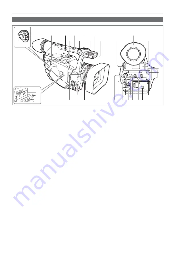
Description of parts
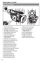
1 POWER switch (Page 20)
2 START/STOP button (Pages 25 and 29)
3 OPEN/EJECT switch (Page 29)
4 REC CHECK button (Pages 25 and 30)
5 HANDLE ZOOM switch (Page 33)
6 Zoom button (Page 33)
7 Handle zoom button (Page 33)
8 Handle START/STOP button
(Pages 25 and 29)
9 Pin hole (for zoom ring) (Page 13)
10 Built-in stereo microphone (Page 52)
11 Tally lamp (Front) (Page 20)
12 Remote control sensor (Front)
13 Cassette holder (Pages 29 and 30)
14 Cassette cover (Pages 29 and 30)
15 White balance sensor (Page 40)
16 INPUT 1/2 (audio input) switch (Page 52)
17 Lens hood screw (Page 18)
18 P2 card access lamp (x 2) (Page 26)
19 Viewfi nder (Page 21)
20 P2 card slot (x 2) (Page 25)
21 SCENE FILE dial (Page 54)
22 Mode button (Page 25 and 29)
23 Mode lamp (Page 25 and 29)
24 Remote control sensor (Rear)
25 Tally lamp (Rear) (Page 20)
26 MEDIA (P2/TAPE) switch
(Pages 25 and 29)
27 EVF DTL button (Page 22)
28 Power terminal (Page 17)
29 AUDIO control (Page 53)
30 DC INPUT terminal (7.9 V)
31 Battery release button (Page 17)
PUS
H
3
5
7
10
12
9
11
13
14
1
2
4
6
8
18
19
20
21
23 25 27 29
22
24 26 28
31
30
15
17
16
2
1
Right side and rear side
Summary of Contents for AGHVX200P - MEMORY CARD CAMCORDER
Page 133: ...Memo 133 ...


