background image

Aicure ANUP5255V2


  UV irradiation 


41 


9.2


Operation on the main screen 


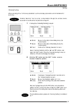
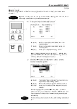
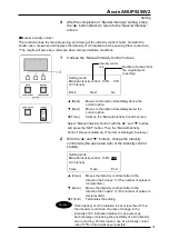
UV irradiation, “UV control” ON/OFF switching, and “Intensity check” should be performed on the 
“main screen”. 
On “the main screen”, the settings and lamp use status can be checked. 


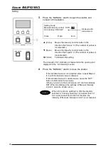
UV control    OFF 
UV intensity    0800 mW 
Manual intensity control    40% 


Back 

Next 

On 


The functions of the “

”, “

” and “SET” buttons vary 

depending on the screen. 
The three buttons should be operated according to the 
functions shown in the lower part of each screen. 


[Ex.] When the above item selection screen is shown 

  (Back) 

Moves to the option immediately above the 
current option. 

  (Next) 

Moves to the option immediately below the 
current option. 

SET (On) 

Turns UV control to ON (in UV control OFF 
situations) 


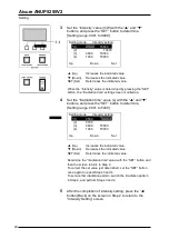
When in “the setting mode”, pressing the “

” button and the 

“SET” button at the same time terminates the setting mode, 
calling up the main screen. 
If no buttons are pressed for one minute, the setting mode 
automatically terminates, and the main screen appears. 


Summary of Contents for Aicure ANUP5255V2

Page 1: ...Matsushita Electric Works Machine Vision Ltd Aicure ANUP5255V2 UV Curing System Operation Manual ...

Page 2: ... power cord before repairing or adjusting this product There are high voltage circuits in this product Do not operate this product with any live section exposed Do not repair or adjust it while the power is on Otherwise you may receive an electrical shock Make sure to ground this product Otherwise you may receive an electrical shock Before removing the cover to replace the lamp leave the lamp swit...

Page 3: ...th will sustain damage 6 If the cover is removed do not leave the lamp on for a long time otherwise the lamp or the product itself may become overheated and sustain damage 7 When opening closing the shutter using an external signal or controlling the timer turn off the MANUAL switch on the control panel otherwise MANUAL switch operation takes precedence over control by external signals and timer o...

Page 4: ......

Page 5: ...between Auto and Manual 38 9 UV irradiation 39 9 1 About UV irradiation 39 9 2 Operation on the main screen 41 10 Setting and UV irradiation by external devices 47 10 1 Control items by external devices 47 10 2 EXT IN parallel signal control 48 10 3 RS 232 C serial command control 50 11 How to replace the lamp 61 11 1 Replacement of the lamp 61 11 2 Clearing the total lighting hours of the lamp 63...

Page 6: ...faulty curing due to lamp degradation with time Digital display for minimum variation in settings between operators Adoption of optical feedback control and digital display systems has allowed UV irradiation intensity to be set from an LCD panel realizing high repeatability and easy quantitative setting This reduces variations in irradiation intensity improving curing quality Easy maintenance Adop...

Page 7: ...r type or other irradiation conditions are changed perform calibration again Otherwise the indicated intensity will differ from the actual one 3 When the UV irradiation intensity setting or the setting pattern is changed or after the lamp is replaced check the intensity Otherwise incorrect intensity may be caused in the initial irradiation stage 4 If possible set the UV intensity control rate to 1...

Page 8: ...he external device see Control by External Device EXT IN parallel signal control RS 232 C serial command control Assembly Page 9 Attaching the lamp Installing the light guide fiber unit Connecting the power cord Installation Page 14 Setting Power ON The lamp turns on Page 16 Setting mode Page 17 Reference intensity setting Calibration setting Intensity selection Intensity setting Special intensity...

Page 9: ...e 5 UV irradiation Power ON The lamp turns on Page 16 UV irradiation Page 39 Intensity check UV irradiation auto control UV irradiation manual control LED indication Displaying the time and other settings Power OFF The lamp turns off Page 16 ...

Page 10: ... install a light guide fiber unit when using the Aicure There is a variety of light guide fiber units Select one according to the number of branches and irradiation diameter required Refer to Page 74 Heat ray cutting filter unit Attach this unit to the light guide fiber unit light inlet side when the temperature of the irradiation target area needs to be reduced Refer to Page 66 Lens unit Attach t...

Page 11: ... fiber mount ring LCD panel Displays operation conditions settings and error messages button button Used for screen switching and setting entry SET button Confirms entered data MANUAL switch Opens Closes the irradiation shutter AUTO switch Starts timer control of the irradiation shutter POWER switch Powers on the Aicure LAMP ON OFF switch Turns the lamp on off ...

Page 12: ...with external equipment personal computer PLC etc to transmit receive control signals Ground terminal RS232C terminal D Sub 9 pins male To be connected with a personal computer PLC etc to transmit data on UV intensity and intensity control rate Refer to Page 50 EXT IN terminal D Sub 15 pins female To be connected with external equipment to transmit receive control signals Refer to Page 48 ...

Page 13: ... assembling the Aicure 5 1 Installation of the lamp Do not touch the lamp with the bare hands When installing the lamp wear clean gloves or use gauze 1 Remove the four screws and the left hand cover from the unit 2 Remove the two screws from the lamp mounting base Lamp mounting base Left hand cover Caution Caution ...

Page 14: ...amp and the base The presence of dust or burrs displaces the lamp electrode reducing the intensity of UV irradiation 4 Secure the lamp with the two screws removed in Step 2 5 Remove the top screw install the negative lead wire short to the lamp shaft secure the wire with the removed screw Caution Aicure side D Sub 15 pins female Check that the wire is marked with Negative lead wire Lamp mounting b...

Page 15: ...ke sure not to mistake the positive and negative polarities of the lead wires when connecting them Otherwise the lamp will not operate When connecting the negative lead wire make sure that the lamp is not subjected to any load Otherwise it may be damaged 7 Reinstall the left hand cover Positive lead wire Lamp bottom Negative lead wire Positive lead wire Caution ...

Page 16: ...st and burrs from between the flange of the lamp and the base The presence of dust or burrs displaces the lamp electrode lowering the intensity of UV irradiation When inserting the light guide fiber unit into the mount ring make sure that the UV intensity monitor fiber is on the right hand and insert the fiber unit as far as it will go Otherwise the indicated intensity will differ from the actual ...

Page 17: ...the monitor fiber mount ring as far as it will go and secure the unit with the screw loosened in Step 3 5 3 Power cord connection Connect the attached power cord to the AC input connector on the rear of the unit After installing the unit connect the power plug to a receptacle Screw Monitor fiber mount ring UV intensity monitor fiber ...

Page 18: ... do not place this product back to back with other machines 5 The unit itself is 210 mm wide 260 mm deep and 284 mm high however dimensions after installation of the light guide fiber unit should be taken into account 6 The minimum tolerable folding radius of the light guide fiber unit is 100 mm Folding into a radius smaller than 100 mm may damage the unit Do not touch the light guide end with the...

Page 19: ...according to the size of the irradiated area of a workpiece irradiation diameter and the intensity of UV irradiation For the relationship between the irradiation distance and the irradiation diameter see the table at the Page 72 Irradiation distance Irradiation distance Irradiation diameter ...

Page 20: ...ter the stoppage or after the lamp is stabilized After the LED of the LAMP ON OFF switch illuminates UV irradiation can be started 7 2 Power OFF The lamp goes out 1 Press the LAMP ON OFFF switch The LED of the LAMP ON OFF switch goes out Ten minutes later the cooling fan stops Lighting up the lamp again should be done after the stoppage of the cooling fan If the lamp won t illuminate retry it afte...

Page 21: ...ensity Mnual intensity control 40 Back Next Go The main screen appears For the details see 7 Power ON OFF 2 Press the button and the SET button at the same time Setting mode Reference intensity setting Calibration setting Back Next Go The setting mode screen appears Pressing the and buttons switches from a setting item to another How to exit from the setting mode When in the setting mode re pressi...

Page 22: ...selection screen is shown Back Moves to the option immediately above the current option Next Moves to the option immediately below the current option SET Go Calls up the selected setting item Pressing the button and the SET button at the same time terminates the setting mode displaying the main screen If no buttons are pressed for one minute the setting mode automatically terminates and the main s...

Page 23: ...intensity Set the irradiation conditions of the special intensity two patterns Special intensity Manual intensity control The intensity control shutter can manually be opened and closed The intensity of UV irradiation with the shutter open is measured and displayed It is appropriate for the determination of irradiation conditions Manual intensity control Shutter timer Set the shutter timer ON OFF ...

Page 24: ...uld be measured with a commercial UV power meter Harmonize the type of fiber and the irradiation distance with the actual conditions and take care that the UV power meter and fiber are not displaced until calibration is completed The displacement causes the display intensity not to match the actual intensity If any of the irradiation conditions such as the irradiation distance and the type of fibe...

Page 25: ...3000 Up Down Set Up Increases the indicated value Down Decreases the indicated value SET Set Determines the indicated value After the message Reference Intensity Setting Completed is displayed the screen switches to the Calibration screen Reference Intensity Setting Completed Calibration Reference intensity 3000 Back Back Go Back Returns to the Reference Intensity Setting Calibration Setting scree...

Page 26: ...ting screen Back Interrupts calibration and returns to the Reference Intensity Setting screen SET Go Switches to the Calibration screen 2 Press the SET button to call up the Calibration screen Calibration 080 pulses Current intensity Enter intensity Back Back End Back Returns to the previous screen SET End Returns to the Reference Intensity Setting Calibration Setting screen 3 After the display Sh...

Page 27: ...T button Calibration 080 pulses Current intensity 2800 Enter intensity 2800 Up Down Set Up Increases the indicated value Down Decreases the indicated value SET Set Determines the indicated value The screen switches to the Calibration screen as the next step Calibration 180 pulses Current intensity Enter intensity Back Back End Repeat steps 3 to 6 until Calibration terminates Pulse indication switc...

Page 28: ...to four step irradiation UV1 to UV4 Up to four steps of irradiation are available The intensity and duration of UV irradiation can be switched Select from among the irradiation patterns UV1 to UV4 and combine them Execute the irradiation patterns UV1 to UV4 in ascending order by the number at the end of the pattern name The intensity and duration of each irradiation pattern should be set in Intens...

Page 29: ... should be set in Special Intensity Start of the second step UV irradiation can be controlled with the interval timer ON and the AUTO signal AUTO button OFF Analog irradiation UV6 The intensity of UV irradiation is varied in an analog fashion within a given time period The intensity initial and final and duration of UV irradiation should be set in Special Intensity Intensity When U1 to UV3 are sel...

Page 30: ... number of times It is not allowed when UV5 or UV6 is selected When UV5 is selected no other irradiation pattern can be selected When UV6 is selected no other irradiation pattern can be selected Setting mode Intensity selection 1 2 3 4 Special intensity 5 6 Back Next Set Back Terminates Intensity Selection and returns to the Reference Intensity Setting Calibration Setting screen Next Moves the irr...

Page 31: ...t Intensity Setting with the and buttons and press the SET button Then the Intensity Setting screen is called up The item is displayed inversely 2 With the button and the SET button select a desired irradiation pattern Setting mode Intensity setting 1 0500 T0003 2 0700 T0003 3 0800 T0003 4 1000 T0003 Back Next Set Back Terminates Intensity Selection and returns to the Intensity Setting screen Next...

Page 32: ...he and buttons and press the SET button to determine Setting range 0001 to 5400 Setting mode Intensity setting 1 0500 T0003 2 0700 3 0800 T0003 4 1000 T0003 Up Down Set Up Increases the indicated value Down Decreases the indicated value SET Set Determines the indicated value Determine the Irradiation time value with the SET button and then the screen returns to Step 2 To correct the set value just...

Page 33: ...l Intensity with the and buttons and press the SET button Then the Special Intensity screen is called up The item is displayed inversely 2 With the button and the SET button select a desired irradiation pattern Setting mode Special Intensity 5 0500 T0003 T0003 1000 T0003 6 0500 T0010 1000 Back Next Set Back Terminates Special Intensity and returns to the Special Intensity Setting screen Next Moves...

Page 34: ... 6 0500 T0010 2000 Up Down Set Up Increases the indicated value Down Decreases the indicated value SET Set Determines the indicated value When the value is determined by pressing the SET button the screen for setting the next item is called up Until all the setting operations are completed repeat Step 3 When completed the screen returns to Step 2 To correct the set value just determined set the SE...

Page 35: ... with the and buttons and press the SET button Then the Manual Intensity Control screen is called up The item is displayed inversely 2 With the and buttons change the intensity control rate the open area ratio of the intensity control shutter Setting mode Manual intensity control 100 000 UV intensity Close Open End Close Moves the intensity control shutter in the direction that closes it The numbe...

Page 36: ... at the opening and displayed in the UV Intensity section 4 Press the MANUAL switch to close the shutter If the indicated value is not a desired value repeat Steps 2 to 4 until the desired value is obtained If the indicated value is a desired value press the SET button to determine the set value When you return to the main screen UV control is already OFF When irradiating at the settings of Manual...

Page 37: ... option immediately below the current option SET Go Goes into the Shutter Timer screen Select Shutter Timer Lamp Change Time with the and buttons and press the SET button Then the Shutter Timer screen is called up The item is displayed inversely 2 Set the Shutter Timer indicated value open time with the and buttons and press the SET button Setting range 0001 to 5400 s Setting mode Shutter timer 00...

Page 38: ...e cumulative lamp ON time on the main screen before this setting operation 1 Set the Lamp Change Time indicated value life with the and buttons and press the SET button Setting range 0001 to 3000 h Setting mode Lamp change time 3000 Hour Up Down Set Up Increases the indicated value Down Decreases the indicated value SET Set Determines the indicated value Press the SET button to return to the Shutt...

Page 39: ...the Address Setting screen Setting mode Address setting Language switching Back Next Go Back Moves to the option immediately above the current option Next Moves to the option immediately below the current option SET Go Goes into the Address Setting screen Select Address Setting with the and buttons and press the SET button Then the Address Setting screen is called up The item is displayed inversel...

Page 40: ...g Japanese Back Change End Change Setting mode LANGUAGE English Back Change End Back Returns to the Address Setting screen Change Switches between Japanese and English SET Set Terminates the setting and returns to the Address Setting screen 2 After selecting the language press the SET button to determine the language setting When the SET button is pressed the language used to display on the LCD pa...

Page 41: ...conduct origin return Setting mode Origin Return Back Next Go Back Moves to the option immediately above the current option Next Moves to the option immediately below the current option SET Go Executes Origin Return Select Origin Return with the and buttons and press the SET button Then Origin Return is executed Setting mode Returning to the origin Setting mode Completed After the Completed messag...

Page 42: ...Go Goes into the Control screen Select Control with the and buttons and press the SET button Then Control screen is called up 2 Every time the button is pressed UV control is switched between Auto and Manual Setting mode Control Auto Back Change End Back Returns to the Control screen Change Switches between Auto and Manual SET End Terminates the setting and returns to the Control screen 3 After se...

Page 43: ...eset irradiation pattern and automatically terminated The shutter is closed Execute Intensity check Execution of check of the intensity setting from UV1 to UV4 Press the MANUAL switch to start UV irradiation Intensity settings are switched among UV1 to UV4 by external signals Note 5 The shutter is opened Press the MANUAL switch to terminate UV irradiation The shutter is closed Note 1 In case of UV...

Page 44: ...ys operation conditions settings and error messages button button Used for screen switching and setting entry SET button Confirms entered data MANUAL switch Opens Closes the irradiation shutter AUTO switch Starts timer control of the irradiation shutter ...

Page 45: ... The three buttons should be operated according to the functions shown in the lower part of each screen Ex When the above item selection screen is shown Back Moves to the option immediately above the current option Next Moves to the option immediately below the current option SET On Turns UV control to ON in UV control OFF situations When in the setting mode pressing the button and the SET button ...

Page 46: ...ntrol ON is established the intensity is adjusted to the value selected in Intensity selection If UV control OFF is established the intensity is measured at the current position and displayed Intensity check Shutter timer Illumination time Change time Displays the shutter timer value set in the setting mode Displays the cumulative lamp illumination time Displays the lamp change time set in the set...

Page 47: ...ontrol the main screen with the and buttons UV control OFF UV intensity 0800mW Manual intensity control 40 Back Next ON Back Moves to the option immediately above the current option Next Moves to the option immediately below the current option SET ON OFF Switches UV control between ON and OFF Press the SET button to switch UV control between ON and OFF UV control ON UV intensity 0800mW Manual inte...

Page 48: ...n Intensity check 1 0700 T0003 2 1000 T0003 3 1500 T0003 4 2000 T0003 Back Next Help Back Returns to the main screen Next Goes into the Intensity Check screen SET Help Press the button to get into the Intensity Check screen Press the MANUAL button to open the shutter The patterns indicated by selected in Intensity Selection sequentially undergo UV intensity adjustment After a given period of time ...

Page 49: ...r Displays the irradiation time of Auto UV irradiation when UV control is OFF Set in the setting mode Illumination time Displays the cumulative lamp ON time Change time Displays the lamp change time set value Set in the setting mode Intensity setting detail This function displays the Intensity setting value set in the setting mode With the and buttons select the Intensity setting detail screen Int...

Page 50: ...ely below the current option SET Clear Clears the cumulative lamp time 3 seconds or more 2 Press the SET button for 3 seconds or more to reset the cumulative lamp ON time to 0 Rewrite protection for setting details Setting mode switching and UV control ON OFF operation can be protected 1 On the main screen press the and buttons at the same time until the Lock ON display is given When the button is...

Page 51: ...tive pages on setting through the LED panel and UV irradiation by switch operation Controllable by external device Control item Parallel EXT IN terminal Serial RS 232 C terminal Descriptive page on setting and operation Reference intensity setting 20 Calibration 22 Intensity selection 24 Intensity setting 27 Special intensity setting 29 Manual intensity control 31 Shutter timer ON OFF time 33 Lamp...

Page 52: ...heck begins When the contacts open intensity check terminates UV irradiation Auto UV irradiation begins Operates the same as the AUTO switch does When the contacts short one shot Auto UV irradiation begins UV irradiation Manual Shutter Open Close Operates the same as the MANUAL switch does When the contacts short manual UV irradiation begins the shutter opens When the contacts open UV irradiation ...

Page 53: ...amp comes on the output turns on Ready Lamp stabilized When the lamp ON state becomes stabilized the output turns on UV irradiation is ready Fault detection When some fault occurs in the AICURE body the output turns on Connection diagram The ratings of a load to be connected to the signal output should be as follows Voltage 24 V maximum Current 100 mA maximum Internal circuit The ratings of the ON...

Page 54: ...ernal device When sending a command specify the address device number For the address see Chapter 8 Address Setting Language Switching Command list Command code Command type Control detail RS UV intensity readout Reads the intensity value displayed on the LCD RK Intensity control rate readout Reads the intensity control rate displayed on the LCD RU Intensity setting value readout Reads the intensi...

Page 55: ...s 51 Basic format Command Header Address 00 31 Identification code Command code Text Terminator C R Response Normal Header Address 00 31 Identification code Command code Text Terminator C R Abnormal Header Address 00 31 Identification code Error code Terminator C R ...

Page 56: ...peed 9600 bps Communication method Full duplex Synchronization Start stop synchronization Transmission coverage Within 15 m Transmission code ASCII code Data length 8 bits Parity check None Data format Stop bits 2 bits BCC Block Check Code None Aicure side D Sub 9 pins male RS232C port of the Aicure RS232C port of the personal computer DOS V Pin No Signal name Pin No Signal name ...

Page 57: ...ce RS UV intensity readout Reads the latest UV intensity value measured Command Response RK Intensity control rate readout Reads the latest intensity control rate measured Command Response Intensity value data 4 digit Address Address Intensity control rate data 4 digit Address Address ...

Page 58: ...ing type 1 digit Timer setting value 4 digit Intensity rate data 4 digit Address Address Address First step intensity setting value 4 digit First step timer setting value 4 digit Setting value of wait time until second step 4 digit Second step intensity setting value 4 digit Second step timer setting value 4 digit Starting intensity setting value Total irradiation time Ending intensity setting val...

Page 59: ...l devices 55 RUS Intensity selection readout Reads the presence or absence of selection of intensity settings U1 to U6 Command Response Address Address Presence or absence of intensity setting 1 Selected 0 Not selected Ex When U1 and U2 are selected 110000 ...

Page 60: ...s 56 RT Lamp ON time readout Reads the cumulative lamp ON time stored in the body and the presence or absence of lamp change time Command Response Address Address Cumulative illumination time Lamp change time signal 1 ON 0 OFF ON from 30 minutes before change time ...

Page 61: ...nsity selection Command Response At normal reception the command message is returned as is However is changed to Address UV intensity selection data 1 Selected 0 Not selected Ex When U3 and U4 are selected 001100 Address UV intensity selection data 1 Selected 0 Not selected Ex When U3 and U4 are selected 001100 ...

Page 62: ...ing value write Sets changes the UV intensity setting values UV1 to UV6 Command When set in UV1 to UV4 Response At normal reception the command message is returned as is However is changed to Address Setting pattern Address Same as the command Irradiation intensity Irradiation intensity ...

Page 63: ...Response At normal reception the command message is returned as is However is changed to Same as the command Address Address Setting pattern 5 First step irradiation intensity First step irradiation time Wait time until second step Second step irradiation intensity Second step irradiation time ...

Page 64: ...anged during transmission 21 Parity error When the parity was valid the parity check on reception detected an error 22 Overrun error On reception the CPU was late for readout of received data 23 Data immediate error This is because an error occurred immediately after data transmission or reception 40 Format error The command transmission format is not correct Ex is absent 41 Command Undefined erro...

Page 65: ...least 10 minutes to allow it to cool After replacing the lamp make sure to execute total illumination time clearing 11 1Replacement of the lamp Do not touch the lamp with the bare hands When installing the lamp wear clean gloves or use gauze 1 Remove the four screws and the left hand cover from the unit 2 Remove the top and bottom screws and the two lead wires 3 Remove the two screws that secure t...

Page 66: ...ards Keep dust and burrs from between the flange of the lamp and the base The presence of dust or burrs displaces the lamp electrode lowering the intensity of UV irradiation 6 Secure the new lamp to the lamp mounting base with the two screws removed in Step 3 7 Install the negative lead wire short to the lamp shaft and secure it with the screw removed in Step 2 Flange Lamp Lamp mounting base Cauti...

Page 67: ... sure not to mistake the and polarities of the lead wires when connecting them Otherwise the lamp will not operate When connecting the lead wire make sure that the lamp is not subjected to any load Otherwise it may be damaged 9 Reinstall the left hand cover 11 2Clearing the total illumination time See P 46 Caution Negative lead wire Positive lead wire ...

Page 68: ...ent for at least 30 minutes after turning off the lamp 1 Before reinstalling the left hand cover after replacing the lamp according to Section 11 1 remove the six screws and the right hand cover 2 Replace the used positive lead wire with a new one and correctly wire it Make sure to install the new wire in the correct direction 3 Reinstall the left and right hand covers When reinstalling the covers...

Page 69: ... unit 12 1UVIncreasing UV irradiation intensity Lens unit To collect UV light for higher UV intensity use a lens unit 1 Insert the lens unit into the UV ray outlet of the light guide fiber unit 2 Tighten the two hexagonal socket head screws with a hexagonal wrench 3 mm Do not scratch the lens or touch it with bare hands If the lens is dirty gently wipe it with a cloth damped with alcohol Caution L...

Page 70: ...m 254 nm to 436 nm and filters out heat rays with wavelengths longer than 436 nm Install the heat ray cutting filter unit in the light guide fiber unit before installing the fiber unit in Aicure 1 Install the heat ray cutting filter unit in the installation section side of the light guide fiber unit 2 Insert the light guide fiber unit in the installation section of the Aicure body and secure the u...

Page 71: ...and cover is not in place or its screws are loosened the lamp will not light 2 Protection from overheating The power supply circuit and the optical section of the machine have thermal circuits In cases of overheating the circuits will start operation to turn off the lamp 3 Protection from overcurrent To protect the machine from overcurrent fuses 6 3 A are provided for the power supply circuit boar...

Page 72: ...y excessive force to the glass 1 Pull the fuse holder out of the power supply socket 2 Remove the blown fuse 3 Remove the spare fuse and replace the blown fuse with the spare one 4 Reinstall the fuse holder It is recommended that the fuse holder should be replenished with a new spare fuse 6 3A 5 2 mm dia x 20 mm while the Aicure is not in operation Caution Press out Fuse holder Power supply socket...

Page 73: ...l life The intensity of UV irradiation is low 1 Is the lamp loosened 2 Is dust attached to the lamp mount Dismount the lamp and check 3 Is the lamp at the end of its useful life 4 Is the light guide fiber unit soiled If the lens is soiled wipe it with alcohol The shutter does not operate 1 Are the operation section and the external control terminal used concurrently 2 Is the shutter solenoid at th...

Page 74: ... OFF turn the POWER to ON again and leave until the cooling fan stops for 10 minutes Overheat The temperature inside the body rises abnormally high With the POWER switch ON turn the LAMP ON OFF switch to OFF and leave for 10 minutes Caution Shutter error Irradiation shutter failure Contact the store from which you made purchase The cumulative lamp OFF time is approaching the lamp change time 30 ho...

Page 75: ...al intensity setting Intensity control enabled range 000 100 Address Device number 00 31 Function Language switching Selectable between Japanese and English Control signal D Sub 15pin Output Lamp ON confirmation signal Lamp Stable signal Shutter Open confirmation signal Error notification signal Input Lamp ON command Shutter Open command Shutter Auto command Intensity check command Communication s...

Page 76: ...P5051BS With BS lens 1066mw cm2 φ8 0 mm 953 φ7 5 1690 φ6 0 4762 φ3 0 3940 φ4 0 2988 φ5 5 1317 φ8 5 770 φ11 272 φ16 161 φ20 ANUP3051 Without lens 5742mw cm2 φ2 5 mm 3465 φ3 0 1698 φ5 5 923 φ7 5 428 φ9 391 φ12 213 φ13 135 φ20 41 φ37 25 φ40 ANUP3051AS With AS lens 2031mw cm2 φ5 0 mm 5073 φ3 0 6356 φ2 5 3071 φ4 5 1881 φ5 5 1216 φ6 5 637 φ7 5 377 φ9 120 φ13 71 φ17 3 5 mm diameter straight bundle ANUP30...

Page 77: ...Aicure ANUP5255V2 Dimensional drawing 73 16 Dimensional drawing Rubber foot Optical fiber Power cable Cooling fan Output position ...

Page 78: ...5mm 3 3 5mm 8 8mm Example Bundle diameter 5 mm Number of branches 2 Equipped with a heat ray cutting filter unit The part number to be ordered is ANUP5052EN Spare parts It is recommended that spare parts are always kept in stock Item Specifications Order number Lamp Preset type 250 W ultra high pressure mercury lamp Operating life 3 000 hours Reliability assured life 2 000 hours 40 or more of the ...

Page 79: ...issue Revised point Oct 19 2001 First issue Close attention was paid to the preparation of this manual however if you find any errors please inform us at the following address Matsushita Electric Works Machine Vision Ltd 1048 Kadoma Kadoma city Osaka 571 8686 Japan ...

Reviews: