- 43 -
5) Operation of device
4. Action sequence
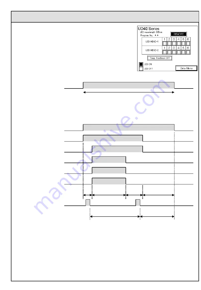
(1) Switching
to “REMOTE” mode
By turning #1 pin of D-Sub37 connector to ON, UD40 controller
switches to “REMOTE” mode, where “REMOTE” display
appears on main screen and control by signals from D-Sub37
connector is enabled.
Main screen
(2) Changing program No.
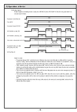
Program No. can be modified by setting the program No. to be selected with the 5 bits of #4 to 8 pins of
D-Sub37 connector and feeding one-shot pulse signal of 0.3 second or longer to #3 pin.
ON
Local / remote switching (1)
Control by external signal is enabled.
ON
ON
ON
ON
ON
ON
ON
ON
Local / remote switching (1)
Program No. bit-0 (4)
Program No. bit-1 (5)
Program No. bit-2 (6)
Program No. bit-3 (7)
Program No. bit-4 (8)
Program No. to be set
Program No. change pulse (3)
Program No. set
1
Program No.1
31
3
0
Program No.3
Items to note)
Program No. will no be changed by just modifying the 5 bits of #4 to 8 pins of D-Sub37 connector.
Modification of program No. cannot be done without feeding one-shot pulse signal of 0.3 second or
longer to #3 pin.

