– 14 –
VTR Connections
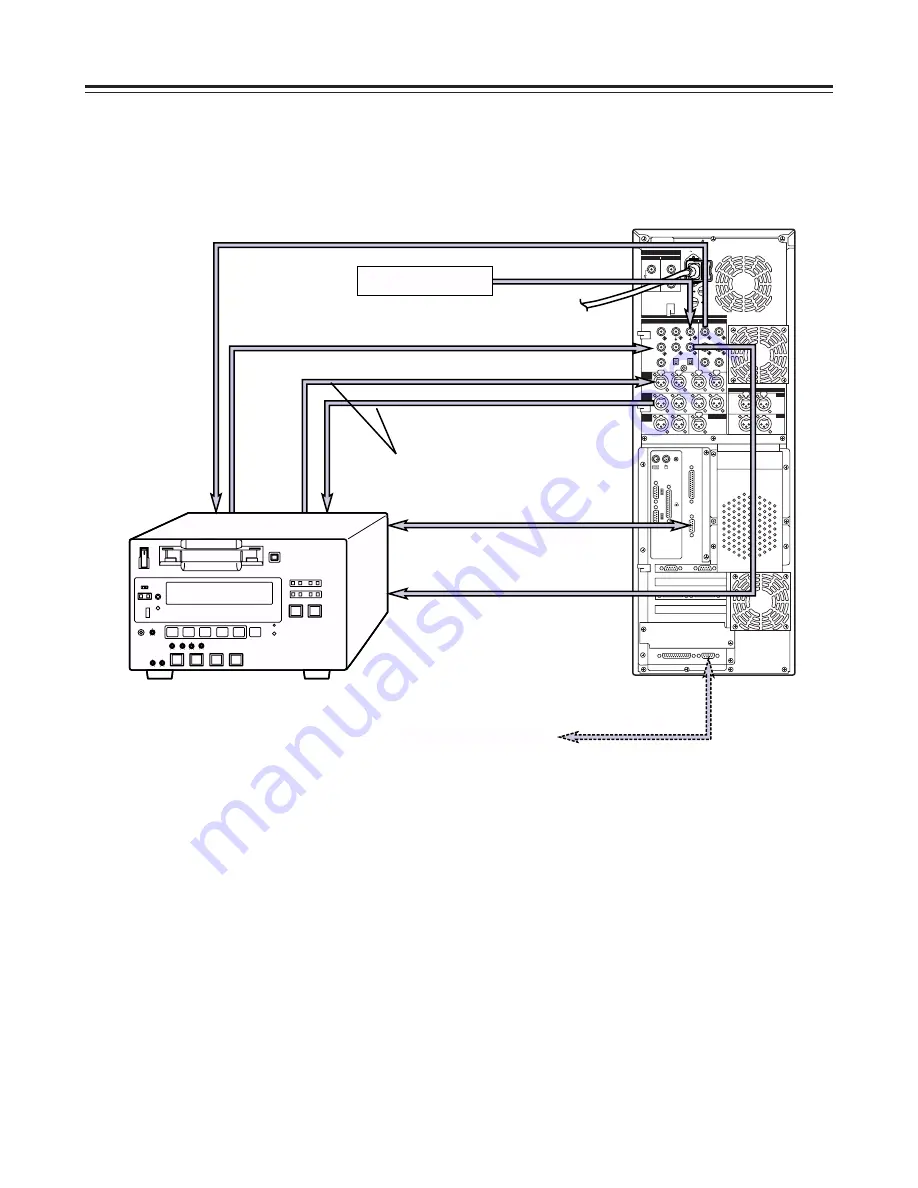
Connect a commercial video cassette recorder/player
Connections
Note:
Set the TAPE/EE selector switch of the external VTR to the TAPE position. (If it is set to EE, the picture may
be unstable and audio may be transmitted.)
If the VTR is not equipped with a TAPE/EE selector switch, use one of the two connection configurations
described below:
1. To use the external VTR for playback only, connect the outputs of the external VTR to the inputs of the
editing system unit.
2. To use the external VTR for recording only, connect the inputs of the external VTR to the outputs of the
editing system unit.
AC IN
FUSE F1
125V
5A
FUSE F2
125V
5A
SIGNAL GND
IN
OUT
1
2
SDI/SDIT
SDI/SDIT
ACTIVE THROUGH
SDI/SDIT
(OPTION)
SDI
Y
ANALOG
VIDEO INPUT
VIDEO OUTPUT
Y
1
2
AUDIO
IN
AUDIO
OUT
AUDIO
MON
TC IN
IN
OUT
D I G I TA L AU D I O
MON
OUT
VIDEO
IN
REF VODEO
IN
PB
PR
PB
PR
ON
OFF
75
≠
ON
OFF
75
≠
CH1
CH2
CH3
PUSH
CH4
CH1
CH2
L
R
RS-232C
SERIAL 1
SERIAL 2
RS-422A
CH1-2
CH3-4
CH3
CH4
PUSH
PUSH
PUSH
PUSH
CH1-2
CH3-4
PUSH
PUSH
Main unit
Coaxial cable
(with BNC connectors)
Coaxial cable
(with BNC connectors)
2-conductor shielded cable
(with XLR-3-12C connectors)
COMPONENT VIDEO OUT
(Y/P
B
/P
R
)
AUDIO OUT (CH1/CH2/CH3/CH4)
RS-422A
External VTR 1
(External VTR 2)
RS-422A
AUDIO IN (CH1/CH2/CH3/CH4)
COMPONENT VIDEO IN
(Y/P
B
/P
R
)
REFERENCE SIGNAL
REFERENCE VIDEO THROUGH OUT


