background image

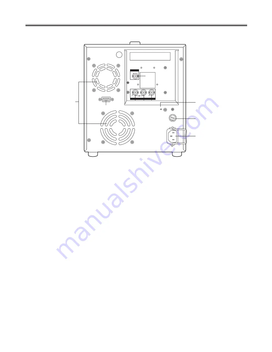
Parts and their functions

6 (E)

1

HD SDI IN connector (BNC)

The HD SDI signals are supplied to this connector.

2

HD SDI through connector (BNC)

The HD SDI input signals are passed straight through the
unit and output here.

3

HD SDI OUT connector (BNC)

The HD SDI signals are output from this connector.

4

REMOTE IN (RS-422) connector

The remote controller is connected to this connector.
The only commands supported in the remote control
mode are FF, REW, STOP, PLAY, REC and SHTL.

<Note>

Functions that cannot be used when an external control
unit is used

O

Clip location function initiated by pressing the SHIFT
key and FF or REW key at the same time

O

Eject control function initiated by pressing the SHIFT
key and REW key on the remote controller (AJ-A95)

5

SD OUT VIDEO connector

The down-converted signals are output from this connec-
tor.

6

AC IN socket

The power cord is connected to this socket.

7

FUSE holder

This contains a 3.15A fuse.

8

SIGNAL GND

To minimize noise, this is connected to the signal ground
on the component connected.  It is not a safety ground.

9

Fan motors

These are used to cool down the unit.

1 2 3

5

4

6

7

8

9

REMOTE IN

SD OUT

HD SDI

VIDEO

IN

ACTIVE THROUGH

OUT

AC IN

~

SIGNAL

GND

FUSE

PUSH

Rear panel

Summary of Contents for AJ-FRC27E

Page 1: ...37 Model No AJ E Operating Instructions Frame Rate Converter Before operating this product please read the instructions carefully and save this manual for future use ENGLISH DEUTSCH FRANÇAIS ITALIANO ESPAÑOL ...

Page 2: ...his mains lead are coloured in accordance with the following code Green and Yellow Earth Blue Neutral Brown Live Caution for AC Mains Lead As the colours of the wires in the mains lead of this appliance may not correspond with the coloured mark ings identifying the terminals in your plug proceed as follows The wire which is coloured GREEN AND YELLOW must be connected to the terminal in the plug wh...

Page 3: ... standard three pin power point which is effectively earthed through the normal house hold wiring Extension cords used with the equipment must be three core and be correctly wired to provide connec tion to earth Wrongly wired extension cords are a major cause of fatalities The fact that the equipment operates satisfactorily does not imply that the power point is earthed and that the installation i...

Page 4: ...unit and a height of 5U Its carrying handle enables it to be carried around for use on location Its ability to enable the images shot to be viewed on the spot and the results of its speed effects to be monitored makes it a wor thy representative of the new style of digital cinema produc tion Notes O This unit is not designed to meet portability drip proof dust proof specifications Bear in mind tha...

Page 5: ...ess the PLAY key and REC key at the same time 8 SHIFT key Press this to search for recorded data To search for a previous clip press the REW key and SHIFT key at the same time to search for a subsequent clip press the FF key and SHIFT key at the same time Keep pressing both the SHIFT key and the 2 down key for more than 2 seconds and a shutdown confirma tion message will appear on END screen of th...

Page 6: ...hen an external control unit is used OClip location function initiated by pressing the SHIFT key and FF or REW key at the same time OEject control function initiated by pressing the SHIFT key and REW key on the remote controller AJ A95 5 SD OUT VIDEO connector The down converted signals are output from this connec tor 6 AC IN socket The power cord is connected to this socket 7 FUSE holder This con...

Page 7: ...ON Control flow when AUTO REC is set to ON There are two recording mode settings AUTO REC ON where data is recorded automatically in accordance with the variable frame rate camera and AUTO REC OFF where data is recorded manually When new data is recorded it is always recorded under a new clip name The clip name is shown on the display panel in the form of a date and time Example The name of the cl...

Page 8: ...ON Operation Forced recording released when AUTO REC mode is established REC PLAY Operation control data Mode REC Start Flag Stop Flag STOP Recording standby mode Recording starts Recording stops Stop released when AUTO REC mode is established Display REC PLAY lamps light REC STOP lamps light REC PLAY lamps light REC STOP lamps light Only STOP lamp lights Auto Rec OFF Operation Forced recording EE...

Page 9: ...d clip is played back Note In the playback mode established immediately after start up the first clip recorded in the unit is selected No clips are selected immediately after all the clips have been cleared O When the SHIFT key and FF key are pressed at the same time the next clip is selected O When the SHIFT key and REW key are pressed at the same time the previous clip is selected Immediately af...

Page 10: ...g the left 1 right 2 down and up keys and press the SET key to estab lish the menu Output location Display panel TC REGEN CONV CONV ORG ORG RS 422 connector CONV ORG SD OUT connector CONV CONV HD SDI OUT connector CONV CONV 3 Output format remaining hard disk drive memory dis play The output format of the currently selected clip appears here For details on the formats which can be output refer to ...

Page 11: ...to the menu selection screen Names of the recorded clips and their durations appear on this screen The clip deletion method is selected on the screen The setup menu settings are performed on this screen Errors and warnings are displayed on this screen LOG screen 1 1 1 1 1 1 T E M P E R R S I L N T B E E P 1 2 3 4 1 U S E R S E T U P H D P B F M T 1 0 8 0 2 4 P 1 2 1 Time occurred The time at which...

Page 12: ...erations are shut down on this screen 1 In the MENU mode press the 1 right key to move the cursor to END shutdown 2 Press the SET key 4 Press the SET key 3 The following message now appears Select YES Note Keep pressing both the SHIFT key and the 2 down key for more than 2 seconds and a shutdown confirma tion message will appear on END screen of this unit 5 The following message now appears 6 Upon...

Page 13: ...essing the REC key on the front panel or the REC and PLAY keys on the remote controller and it is stopped by pressing the STOP key Notes OIf the RecStart signal is detected from the variable frame rate cam era or VTR during FF or REW the unit may be set to the recording mode Select OFF as the Auto Rec setting during FF or REW OThe Auto Rec setting is not saved so it should be changed as required F...

Page 14: ...P OFF ON Default For selecting whether to set the setup level addition function for the SD OUT connector OFF The setup is not added ON The setup is added Note The value which was last selected will be used as the setting when the unit is started up DOWN CONV 525i Default 625i For setting the SD OUT connector Depending on the HD output it may not be possible to select a setting for this item Note T...

Page 15: ...C that conforms with the format which has been set is output dur ing playback User s bit UB display The same user s bit as the one in the HD SDI output signals is displayed Therefore this serves as the input TC during recording and the TC that conforms with the format which has been set is output during playback During recording FF FF II RG FF FF Number of frames recorded in applicable clip If thi...

Page 16: ...29 00T29 00T29 00T29 SD OUT connector 525i 00T29 00T29 00T24 00T24 00T29 00T29 00T29 00T29 SD OUT connector 625i HD SDI OUT connector 00T23 00T23 00T24 00T24 00T29 00T29 00T29 00T29 1080 23 Output format 1080 24 1080 25 1080 50 1080 59 1080 60 720 59 720 60 Example When 1080 23 serves as the format and the SD OUT connector 525 serves as the output location The position where the time code value is...

Page 17: ...ri ance from the output setting F Combination that enables the input to be converted in the pull up mode and then output with normal frames V V mode when the recorded clip signals have been output In the V V mode both rates and formats can be converted Bear in mind that the reference frequency which is output when LOCK has been selected as the INCOME LOCK setting and the reference frequency which ...

Page 18: ...ory delete the files which are no longer needed If free memory is available contact your dealer Data playback is normal in some for mats but not in others Check the input signal and format settings If the data cannot be played back even when a check of the input signal and format settings reveals no problems contact your dealer The images do not always move smoothly with E E mode output The images...

Page 19: ...en this error has occurred but no guarantees can be made for the performance of the hard disk drive Therefore the unit should be moved immediately to a cool place DISK FULL This appears when there is less than the equivalent of 1 minute 60P conversion free mem ory space on the hard disk drive Delete any files which are no longer needed BOOT ERROR This appears when the unit cannot be started up pro...

Page 20: ...ctors HD SDI connector SMPTE 292M standard complied with OUT DIGITAL connectork1 BNC Playback output formats 1080 23 98psf 24psf 25psf 50i 59 94i 60i 720 60P 59 94P 24P 25P 30P 60P Standard down conversion output connector Analog composite signal connectork1 TC UB superimposing ON OFF function provided with SETUP Control connector RS 422 connectork1 Interface connectors HD SDI IN THROUGH HD SDI IN...

Page 21: ...ENGLISH 21 E ...

Page 22: ...Broadcast Europe Ltd West Forest Gate Wellington Road Wokingham Berkshire RG40 2AQ U K Tel 0118 902 9200 Panasonic Broadcast Europe GmbH Hagenauer Str 43 65203 Wiesbaden Biebrich Deutschland Tel 49 611 1816 0 F0702Y1072 Printed in Japan E ...

Reviews: