MECH-8
4-8. Tension Confirmation
SPEC
PLAY:
0.06N ± 0.01N (6gf ± 1gf)
REV:
0.09N ± 0.02N (9gf ± 2gf)
MODE
PLAY, REV
´
1
TAPE
63 min M size blank tape
123min. L size blank tape
(For only L-Cassette playback models)
TOOL
VFK1145A (Tension Meter)
¨
Please calibrate Tension Meter before tension
measurement by the following procedure.
<Calibration of Tension Meter>
1.
Attach the 7 grams calibration plumb to DVCPRO
tape. (It’s tape and plumb are included in
VFK1145.)
2. Set the above tape to the Tension Meter as
shown in figure 4-8-1.
3.
Pull up the tape as speed of 33mm/sec and adjust
the Tension Meter so that the meter shows 7
grams (0.07N).
¨
To calibrate Tension Meter the tape must be pulled
up as the direction of tape path of VTR as shown in
figure 4-8-1.
Figure 4-8-1
1.
Play back the beginning portion of the tape.
2.
Insert the tension meter between S3 post and S4
post as shown in figure 4-8-2.
3. Confirm that the tension value is within the
specification.
Figure 4-8-2
4. Place the unit in REV x1 mode. (To see how to
set REV x1 mode, refer to item “4-20. REV (-1)
Mode Setting Procedure”.
5.
Insert the tension meter between S4 post and S5
post as shown in figure 4-8-3. (Direction is
reverse)
6. Confirm that the tension value is within the
specification. (Read the meter from rear side as
shown in figure 4-8-3.)
7. If it is out of specification, please perform the
Tension Arm Adjustment.
Figure 4-8-3
NOTE :
Play attention not to give some tape damage.
Plumb
Summary of Contents for AJ-HDC27VP
Page 3: ... 3 ...
Page 4: ... 4 ...
Page 6: ... 6 ...
Page 7: ...Printed in Japan FCD0108NCKK71 ...
Page 136: ...ELE 25 9 TP VR and SW Location AUDIO LCD P C BOARD VEP84331B COMPONENT SIDE FOIL SIDE ...
Page 137: ...ELE 26 VIDEO OUT P C BOARD VEP23500B VTR SYSCON P C BOARD VEP86303C COMPONENT SIDE FOIL SIDE ...
Page 138: ...ELE 27 SERVO P C BOARD VEP82224B COMPONENT SIDE FOIL SIDE ...
Page 139: ...ELE 28 VIDEO MAIN P C BOARD VEP83462C COMPONENT SIDE FOIL SIDE ...
Page 140: ...ELE 29 FOIL SIDE DSP MAIN P C BOARD VEP23530B COMPONENT SIDE ...
Page 141: ...ELE 30 VTR MOTHER P C BOARD VEP80B10A RF EQ P C BOARD VEP87104B COMPONENT SIDE COMPONENT SIDE ...
Page 151: ...HEAD BUFFER BLOCK DIAGRAM BLK 6 ...
Page 152: ...BLK 7 RF EQ BLOCK DIAGRAM ...
Page 153: ...HD SDI TX VIDEO MAIN BLOCK DIAGRAM BLK 8 DSP MAIN DSP MAIN DSP MAIN DSP MAIN HD SDI TX ...
Page 155: ...SERVO BLOCK DIAGRAM BLK 10 ...
Page 157: ...VTR SYSCON SD CARD BLOCK DIAGRAM BLK 12 Q1 SD CARD CKK USED USED ...
Page 158: ...POWER MAIN SUB BLOCK DIAGRAM BLK 13 ...
Page 323: ...PRT 2 MECHANICAL CHASSIS ASSEMBLY 1 ...
Page 325: ...PRT 4 MECHANICAL CHASSIS ASSEMBLY 2 ...
Page 327: ...PRT 6 CHASSIS FRAME ASSEMBLY 1 ...
Page 329: ...PRT 8 CHASSIS FRAME ASSEMBLY 2 ...
Page 331: ...PRT 10 CHASSIS FRAME ASSEMBLY 3 ...
Page 333: ...PRT 12 CASSETTE COMPARTMENT ASSEMBLY ...
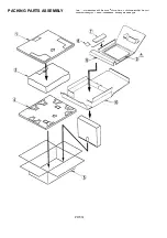
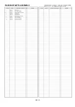
Page 335: ...PRT 14 PACKING PARTS ASSEMBLY ...
Page 387: ...HEAD BUFFER BLOCK DIAGRAM BLK 6 ...
Page 388: ...BLK 7 RF EQ BLOCK DIAGRAM ...
Page 389: ...HD SDI TX VIDEO MAIN BLOCK DIAGRAM BLK 8 DSP MAIN DSP MAIN DSP MAIN DSP MAIN HD SDI TX ...
Page 391: ...SERVO BLOCK DIAGRAM BLK 10 ...
Page 393: ...VTR SYSCON SD CARD BLOCK DIAGRAM BLK 12 Q1 SD CARD CKK USED USED ...
Page 394: ...POWER MAIN SUB BLOCK DIAGRAM BLK 13 ...
Page 399: ...CBA 5 FOIL SIDE CCD SENSOR P C BOARD VEP20854A FOIL SIDE IC101 E1 IC201 C1 IC301 A1 ...
Page 499: ...ELE 25 9 TP VR and SW Location AUDIO LCD P C BOARD VEP84331B COMPONENT SIDE FOIL SIDE ...
Page 500: ...ELE 26 VIDEO OUT P C BOARD VEP23500B VTR SYSCON P C BOARD VEP86303C COMPONENT SIDE FOIL SIDE ...
Page 501: ...ELE 27 SERVO P C BOARD VEP82224B COMPONENT SIDE FOIL SIDE ...
Page 502: ...ELE 28 VIDEO MAIN P C BOARD VEP83462C COMPONENT SIDE FOIL SIDE ...
Page 503: ...ELE 29 FOIL SIDE DSP MAIN P C BOARD VEP23530B COMPONENT SIDE ...
Page 504: ...ELE 30 VTR MOTHER P C BOARD VEP80B10A RF EQ P C BOARD VEP87104B COMPONENT SIDE COMPONENT SIDE ...
Page 554: ...PRT 2 MECHANICAL CHASSIS ASSEMBLY 1 ...
Page 556: ...PRT 4 MECHANICAL CHASSIS ASSEMBLY 2 ...
Page 558: ...PRT 6 CHASSIS FRAME ASSEMBLY 1 ...
Page 560: ...PRT 8 CHASSIS FRAME ASSEMBLY 2 ...
Page 562: ...PRT 10 CHASSIS FRAME ASSEMBLY 3 ...
Page 564: ...PRT 12 CASSETTE COMPARTMENT ASSEMBLY ...
Page 566: ...PRT 14 PACKING PARTS ASSEMBLY ...


