Chapter 7 Menu description tables
78
HD SDI P.SAVE
ON
OFF
For selecting whether to output the HD SDI
signal.
ON:
The HD SDI circuit is set to the power
save mode, and the signal is not output
at any time.
OFF:
The signal output accords with the
position (VTR, CAM or OFF) selected
by the OUTPUT SEL switch.
HD SDI CHAR
ON
OFF
For selecting whether to superimpose
characters on the HD SDI connector signals
in accordance with the position selected by
the CHARACTER switch on the side panel.
ON:
The characters are superimposed and
output.
OFF:
The characters are not superimposed.
DOWNCON CHAR
ON
OFF
For selecting whether to superimpose
characters onto the down-converted signal in
accordance with the position selected by the
CHARACTER switch on the side panel.
ON:
The characters are superimposed and
output.
OFF:
The characters are not superimposed.
HD SDI METADATA ON
OFF
For selecting whether to output the metadata
to the HD SDI signal.
ON:
The metadata is output.
OFF:
The metadata is not output.
DOWNCON
P.SAVE
ON
OFF
For selecting whether to output the down-
converted signal.
ON:
The down-converter is set to the power
save mode, and the signal is not output
at any time.
OFF:
The signal output accords with the
position (VTR, CAM or OFF) selected
by the OUTPUT SEL switch.
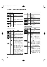
7-2 SYSTEM SETTING
7-2-1 SYSTEM MODE
The underlining in the variable range column indicates the setting in the preset mode.
INTERVAL REC
MODE
ON
ONE SHOT
OFF
For setting the INTERVAL REC function.
ON:
Interval recording is possible in single-
frame units.
ONE SHOT:
Recording is performed only once for the
time set in the REC TIME item, after which
it stops.
OFF:
Interval recording is not performed.
<Note>
The OFF setting is restored when the power
is turned off.
REC TIME
00s01f
:
59s24f
For setting the recording time (one cut).
The shortest time is one frame.
PAUSE TIME
00h00m00s01f
:
00h04m59s24f
:
23h59m59s24f
For setting the recording pause time.
The shortest time is one frame.
C U F
F
S C U F E
C U F
RETAKE MODE
ON
OFF
For selecting whether or not to allow retake
operations (MODE CHECK RET
switch).
<Note>
The OFF setting is restored when the power
is turned off.
F
TAKE TOTAL TIME
NONE
:
5day
For setting the time required for shooting.
Select a setting from NONE (shooting
continues until it is stopped manually) to
5DAY (5 days).
Item/
Data storage
Variable
range
Remarks
Item/
Data storage
Variable
range
Remarks
TOTAL REC TIME
00m00s01f
:
90m59s24f
OVER 100min
NONE
For displaying the total recording time. The
setting for this time cannot be changed.
The total time yielded by adding the REC
TIME, PAUSE TIME and TOTAL TAKE TIME
is displayed.
AUDIO REC
OFF
ON
For setting whether or not to record the
sound.
PRE REC MODE
OFF
0SEC
:
10SEC
For setting the PRE REC function.
OFF:
The PRE REC function is not
operable.
0-10SEC:
The duration for which pre-
recording can be performed after
the REC START button is pressed
is set here.
START DELAY
0SEC
:
10SEC
For setting the time taken until recording is to
start after the REC START button is pressed
in the INTERVAL REC mode.
C U F
C U F
C U F
C U F
Item/
Data storage
Variable
range
Remarks
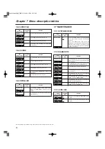
7-2-3 OUTPUT SEL
7-2-2 REC FUNCTION
VF MODE
EE/PB
EE
EE/PB:
The images are played back in the
playback mode.
EE:
The camera images are displayed all
the time.
C U F
C U F
C U F
C U F
C U F
C U F
C U F
OUTPUT CHAR
TC
STATUS
MENU
ONLY
For setting the type of characters to be
superimposed onto the output signals of the
VIDEO OUT connector and HD SDI
connector.
TC:
The time code is displayed. (The menu
appears when the menu is displayed.)
<Note>
The time code display position moves
vertically in accordance with the camera ID
position.
STATUS:
All the same characters as the ones
superimposed on the viewfinder are
displayed. (The menu appears when the
menu is displayed.)
MENU ONLY:
Only appears when the menu is displayed.
Normally, nothing is displayed
<Note>
When ON has been selected as the HD SDI P.SAVE menu
item setting and DOWNCON P.SAVE menu item setting, no
video signals will be output and no audio signals will be output
from the AUDIO OUT connectors (XLR, 5 pins).
CAMERA MODE
50i
25P
For selecting the camera’s operation mode.
50i:
The camera operates in the 50i mode.
25P:
The camera operates in the 25P mode.
01.AJ-HDX400E(VQT0P57)E 05.1.20 15:50 ページ78


