30
Introduction: Control Reference Guide
1.
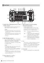
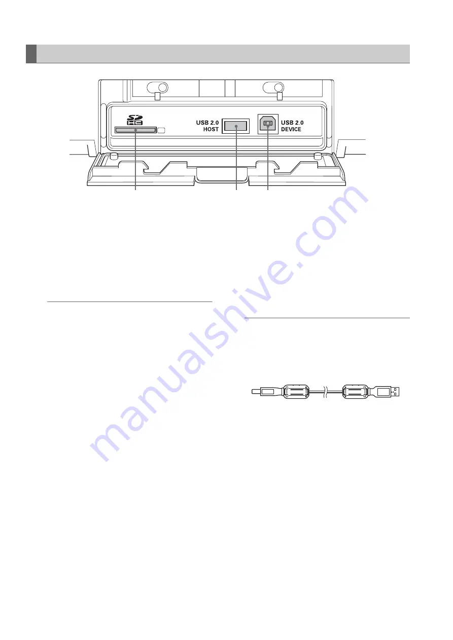
SD/SDHC Memory Card Slot
Insert an SD/SDHC memory card.
Insert the card with the label side facing up and the
end with the corner cut off facing in. Push in the card
until it locks into place. To remove the card, first make
sure that the lamp is not on, then push it in the direction
of insertion to release the lock.
◆
NOTE:
<Precautions in using SD/SDHC memory cards>
• Do not insert any cards other than SD/SDHC memory
cards.
• This unit uses only SD/SDHC memory cards that comply
with the SD/SDHC specifications. Other memory cards
such as MultiMediaCard cannot be used. When using a
miniSD card, be sure to use an adaptor dedicated for use
with the miniSD card to insert the card into the SD Memory
Card Slot.
* MultiMediaCard (MMC) is a registered trademark of
Infineon Technologies AG.
* The SDHC (SD High Capacity) card is a new standard,
established by the SD Card Association in 2006, for
large-scale memory cards with capacities above 2 GB.
• To format an SD card on a PC, use the following software
that can be downloaded from the support sites listed
below.
• This unit supports the following SD and SDHC memory
card capacities.
SD (8 MB to 2 GB): 8 MB, 16 MB, 32 MB, 64 MB, 128 MB,
256 MB, 512 MB, 1 GB, 2 GB
SDHC (4 GB to 16 GB): 4 GB, 8 GB, 16 GB
• For the latest information not available in the Operating
Instructions, visit the P2 support desk at the following Web
sites.
For English: https://eww.pavc.panasonic.co.jp/pro-av/
• The term “SD memory card” will be used below as a
generic for SD and SDHC memory cards.
2.
USB 2.0 connector (Type A)
Connect P2 store and USB 2.0 compliant hard disk
drives for use in the USB host mode.
➝
Refer to “Using USB Connectors” (page 103).
3.
USB 2.0 connector (Type B)
Connect personal computers and other devices for
use in the USB device mode.
➝
Refer to “Using USB Connectors” (page 103).
◆
NOTE:
• Use double shielded cable for making connections to USB
2.0 connectors.
• Attach the supplied ferrite cores near the cable connector
at each cable end when making cable connections to the
USB 2.0 connector.
Side Panel
2
1
3


