ELE-3
2-6. Focus Adjustment
Board
SUB1 BOARD
Spec
6.0kV+/-0.1kV
Chart
Resolution chart
TP
HV Connector (FBT side)
Adjust
RV109 (FOCUS) [SUB1 BOARD]
M.EQ
D.V.M (Use EHV probe)
1. Aim Camera (-recorder) at “Resolution chart” then
adjust zoom and focus so that the full-size picture is
displayed on screen of EVF.
2. Adjust RV109 so that the voltage is within the
specification.
NOTE:
If “2-7 Raster size adjustment” is out of specification,
focus adjustment may not be in the specification. In this
case turn RV110 (H-SIZE) fully counterclockwise then
execute this adjustment again.
If focus voltage is too nigh, High voltage protection
circuits may work. In this case turn power off and turn
RV109 fully counterclockwise then turn power on again.
2-7. Raster Size Adjustment
Board
SUB1 BOARD
Spec
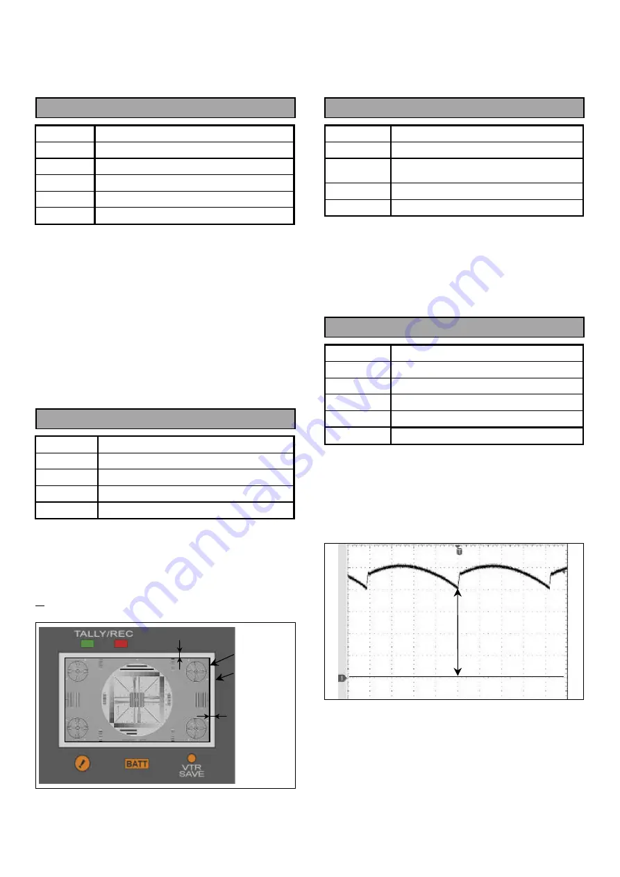
A= approx. 3mm, B= approx. 1mm
Chart
Resolution chart
TP
EVF screen
Adjust
RV110 (H-SIZE), RV106 (V-SIZE)
1. Aim Camera (-recorder) at “Resolution chart” then
adjust zoom and focus so that the full-size picture is
displayed on screen of EVF.
2. Adjust RV106 so that the no picture portion “A” is
within the specification.
3. Adjust RV110 so that the no picture portion “B” is
within the specification.
.
2-8. Heater Voltage Adjustment
Board
MAIN BOARD
Spec
630mV+/-10mV (DC)
TP
TP22-TP23
(CN502 3pin-4pin)
Adjust
RV501 (HEATER V ADJ.)
M.EQ
D.V.M
1. Adjust RV501 so that the Heater voltage between
TP22 and TP23 is within the specification.
NOTE:
Do not set Heater voltage more than “700mV” during
adjustment.
2-9. V Center Adjustment
Board
SUB1 BOARD
Spec
A=more than 4.2V, Picture isn’t clipped
Chart
Resolution chart
TP
CN112 2pin, EVF screen
Adjust
RV112 (V-CENTER)
M.EQ
Oscilloscope
1. Aim Camera (-recorder) at “Resolution chart” then
adjust zoom and focus so that the full-size picture is
displayed on screen of EVF.
2. Adjust RV112 so that the DC voltage A is within the
specification.
3. Confirm picture on the EVF Screen that isn’t clipped.
A
B
Raster edge
CRT frame
A


