background image

51

Setup menus (continued)

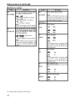
No./Item

Description

USER menu <EDIT>

303

STD/NON-STD

This selects STD or NON-STD in
accordance with the composite input
signal.

0000

AUTO :

Standard/non-standard signals are
automatically identified and
processed.

0001

STD :

Standard signals are processed.
(Forced STD)

0002 N-STD :

Non-standard signals are processed.
(Forced NON-STD)

Notes:

• Use the non-standard (NON-STD)

setting when video or audio trouble
occurs with signals from laser discs or a
satellite.

• At the NON-STD setting, the images

shown on the front panel's LCD monitor
will be significantly disrupted when the
unit's operation is transferred from the
play mode to EE mode: this is normal
and not indicative of malfunctioning.

304

REF LOCK

This selects the REF LOCK mode.

0000

AUTO :

Servo is synchronized with the input
signal during recording, or with the
REF signal during playback.

0001

EXT :

Servo is synchronized at all times with
the REF signal.

0002

AUTO1 :

Servo is synchronized with the input
signal during recording, or with the
REF signal during playback.
When there is no reference (REF)
signal, the EE output is synchronized
with the internal reference signal at
the AUTO setting or with the STD
input signal at the AUTO1 setting.
The AUTO1 setting is selected when
the STD signal is to be used.

Note:

At the AUTO setting, the images shown
on the front panel's LCD monitor will be
significantly disrupted when the unit's
operation is transferred from the play
mode to EE mode: this is normal and not
indicative of malfunctioning. 

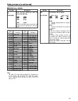
315

AFTER 
CUE-UP

This selects the mode after cue-up
operation is complete.

0000

STOP :

STOP mode

0001

STILL :

SHTL STILL mode

320

VAR FWD MAX

This sets the maximum SLOW FWD
speed.

0000 +4 :

+4x speed

0001 +2 :

+2x speed

0002 +1 :

+1x speed

Note:

At any speed setting other than 0 (+4),
the phase cannot be synchronized from
the editing controller.

321

VAR REV MAX

This sets the maximum SLOW REV
speed.

0000 –4 :

–4x speed

0001 –2 :

–2x speed

0002 –1 :

–1x speed

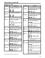
No./Item

Description

323

JOG FWD MAX

This sets the maximum JOG FWD
speed.

0000 +4 :

+4x speed

0001 +2 :

+2x speed

0002 +1 :

+1x speed

Notes:

• The maximum speed is set to +1 x

when the dial on the front panel is
operated.

• At any speed setting other than 0 (+4),

the phase cannot be synchronized from
an editing controller which synchronizes
the phase using the JOG command.

324

JOG REV MAX

This sets the maximum JOG REV
speed.

0000 –4 :

–4x speed

0001 –2 :

–2x speed

0002 –1 :

–1x speed

Note:

The maximum speed is set to –1 x when
the dial on the front panel is operated.

The underlined items indicates the initial setting.

Summary of Contents for AJSPD850P - P2 DECK

Page 1: ...Panasonic Broadcast AJ SPD850p Menu Information ...

Page 2: ...menu screen cursor moves and the item number on the display flashes When the dial is turned clockwise the item number is incremented from 001 002 003 004 and so on conversely when it is turned counterclockwise the item number is decremented When the FF button or REW button is pressed while holding down the PLAY button the next or previous item is selected Whenever possible limit the use of the sea...

Page 3: ...he search dial while holding down the SEARCH button to select whether the lock mode is to be set or released To set the lock mode Set 0001 ON as the setting To release the lock mode Set 0000 OFF as the setting When the lock mode has been set LOCKED flashes on the menu screen The counter display stops flashing and remains lighted 3 To enter the selection made in step 2 for the user file which is to...

Page 4: ...ettings are stored in the memory If the USER1 settings are not to be stored in the memory do not press the SET button but press the MENU button instead Saving user files 1 Press the MENU button 2 Press the REW or FF button while holding down the DIAG or SHIFT button and select USER1 file 3 Turn the search dial to move the cursor on the menu screen to No A01 SAVE 4 Turn the search dial while holdin...

Page 5: ...ect to the video output 0000 100 0100 0 0200 100 The underlined items indicates the initial setting 18 SYS H OFFSET System phase adjustment 0000 3 13 4 µsec 0001 2 8 96 µsec 0002 1 4 52 µsec 0003 0 0 sec 0004 1 4 52 µsec 0005 2 8 96 µsec 0006 3 13 4 µsec Note If setting operation is performed the setting value does not return to factory default setting 19 SYS SC H This sets whether the system phas...

Page 6: ...ining time is displayed on the first line and the total time is displayed in the second line Notes When 2L is selected the remaining time is not displayed if TIME has been selected as the setup menu item No 008 DISPLAY SEL setting When R TTL is selected the total time is not displayed if TIME has been selected as the setup menu item No 008 DISPLAY SEL setting Setup menus continued No Item Descript...

Page 7: ...rs if a warning or error has occurred when T S M has been selected as this setting The recording duration and recording time and date are displayed when the DV format applies The operating status is displayed instead when the DVCPRO50 50 Mbps or DVCPRO 25 Mbps format applies No Item Description 009 CHARA H POS This sets the position of the characters on the horizontal plane for the time code and o...

Page 8: ...GE has been selected only time data is displayed regardless of the setup menu No 008 DISPLAY SEL setting 01 MONTH 02 DAY Sets the month Note If a nonexistent day is set while setting Feb April June September or November it is set as the first day of the following month 0001 JAN 0012 DEC Sets the day Note If a nonexistent day is set while setting Feb April June September or November it is set as th...

Page 9: ...0001 625 Time City region Time City region difference difference 00 00 Greenwich 13 00 00 30 10 30 Lord Howe Island 01 00 Azores 12 00 New Zealand 01 30 09 30 Darwin Islands 02 00 Central Atlantic time 11 00 Solomon Islands 02 30 08 30 03 00 Buenos Aires 10 00 Guam 03 30 Newfoundland 07 30 04 00 Halifax 09 00 Tokyo 04 30 06 30 Rangoon 05 00 New York 08 00 Beijing 05 30 05 30 Bombay 06 00 Chicago 0...

Page 10: ... AUTO EE SEL This selects the memory card recorder mode in which the EE status is established when the MODE switch is set to EE 0000 S F R EE status is established in STOP FF and REW modes However EE status is established at all times when the card is ejected regardless of the MODE switch setting 0001 STOP EE status is established in STOP mode However EE status is established at all times when the...

Page 11: ...L INH This selects whether video input switching using the INPUT SELECT button is to be enabled or disabled 0000 OFF Video input switching using the INPUT SELECT button is enabled 0001 ON Video input switching using the INPUT SELECT button is disabled 0002 REC Video input switching using the INPUT SELECT button after the memory card recorder has been transferred to a recording mode is disabled The...

Page 12: ...S 232C data length Unit bit 0000 7 0001 8 202 ID SEL This sets the ID information to be returned to the controller 0000 OTHER 0001 DVCPRO 0002 ORIG Notes ID information of any VTR except for the DVCPRO s is set in OTHER Select ORIG only when the unit has been connected to the specified controller 207 STOP BIT These settings are for selecting the RS 232C stop bit length Unit bit 0000 1 0001 2 No It...

Page 13: ...r with the STD input signal at the AUTO1 setting The AUTO1 setting is selected when the STD signal is to be used Note At the AUTO setting the images shown on the front panel s LCD monitor will be significantly disrupted when the unit s operation is transferred from the play mode to EE mode this is normal and not indicative of malfunctioning 315 AFTER CUE UP This selects the mode after cue up opera...

Page 14: ...ed 0000 LTC The LTC of the TIME CODE IN connector is used 0001 VITC The VITC of the input video signal is used Note During recording there is a discrepancy in the picture and superimposed TC value displayed but the actual recording is not adversely affected in any way No Item Description 506 BINARY GP This sets the usage status of the user bit of the time code generated by the TCG 0000 000 NOT SPE...

Page 15: ... 100 color bars are generated 0003 CB75 75 color bars are generated 601 OUT VSYNC This selects whether to float the vertical sync position of the video output in order to align the video output phase with the input in the EE record edit modes 0000 N VF Signals are not floated 0001 VF Signals are floated 603 CC F1 BLANK This selects ON or OFF for the closed caption signal of the first field 0000 BL...

Page 16: ...d as the input signals the input information will be recorded Setup menus continued USER menu VIDEO No Item Description 609 EDH This selects whether to superimpose EDH onto the SDI output signals 0000 OFF EDH is not superimposed 0001 ON EDH is superimposed Note Even when ON is selected for this setting EDH is not superimposed onto the signals output from the SDI OUT 3 connector optional if the SUP...

Page 17: ...al is output in its original form 0001 CUT The signal is output with the 7 5 setup removed 0002 ADD The signal is output with the 7 5 setup added No Item Description 623 SETUP 50 For AJ SPD850P Sub screen For setting 7 5 setup processing to be performed on input and output signals in the DVCPRO50 50 Mbps mode When the STOP button is pressed operation is transferred to the sub screen and the setup ...

Page 18: ... selected for the setup menu item No 501 VITC POS 1 and No 502 VITC POS 2 settings cannot be selected for this item 625i system 0000 BLANK 0001 18L 0010 17L 0015 22L 525i system 0000 BLANK 0001 12L 0006 17L 0008 19L The underlined items indicates the initial setting No Item Description USER menu AUDIO 701 CH1 IN LV This selects the audio input CH1 reference level switching 0000 4dB 0001 0dB 0002 2...

Page 19: ...T has been selected by pressing the memory card recorder s AUDIO INPUT SELECT button 0000 ANA Analog input 0001 DIGI Digital input 716 CH2 IN SEL This selects the CH2 input when USER SET has been selected by pressing the memory card recorder s AUDIO INPUT SELECT button 0000 ANA Analog input 0001 DIGI Digital input 717 CH3 IN SEL This selects the CH3 input when USER SET has been selected by pressin...

Page 20: ...YC422 The 422 mode signals are recorded on 1 line 0002 YC411 The 411 mode signals are recorded on 1 line 0003 Y1_B W Only the Y signal is recorded on 1 line directly 0004 Y1_BPF Only the Y signal is recorded on 1 line after it has been separated from the C signal 0005 C1 Only the C signal is recorded on 1 line 0006 Y2_B W Only the Y signal is recorded on 2 lines directly 0007 Y2_BPF Only the Y sig...

Page 21: ...The 422 mode signals are recorded on 2 lines 0002 Y4_B W Only the Y signal is recorded on 4 lines directly 0003 Y4_BPF Only the Y signal is recorded on 4 lines after it has been separated from the C signal 0004 C4 Only the C signal is recorded on 4 lines Notes When a setting from 0001 YC422 to 0004 C4 is selected and the STOP button is pressed operation transfers to the sub screen and the recordin...

Page 22: ...e number of recording lines which was entered as the setup menu No 800 ADD LINE 25 or No 801 ADD LINE 50 setting See Number of lines which can be set for TELETEXT When setting MANU is selected and the STOP button is pressed operation transfers to the sub screen and the number of recording lines can be selected To return from the sub screen press the STOP button again When the input signal is a non...

Page 23: ...deo is not updated for some length of time LCD output is turned off after approximately five minutes To turn off LCD protect mode operate a button or dial on the front panel or start playback through the controller Note that the operation performed to turn off LCD protect mode will be executed USER menu V BLANK The underlined items indicates the initial setting No Item Description 901 BL BRIGHT Th...

Page 24: ... saved No Item Description A02 P ON LOAD This loads the contents of the selected user file into USER1 and it starts operation with the USER1 settings when the power is turned on 0000 OFF Operation is started with the settings of the previously set user file 0001 USER2 The contents of USER2 are loaded into USER1 and operation is started with the USER1 settings 0002 USER3 The contents of USER3 are l...

Reviews: