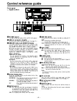
Control reference guide (continued)
– 12 –
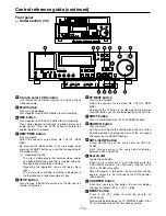
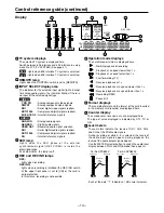
HEADPHONES
PULL
PULL
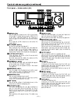
AUDIO MIX
1&2
CH1/3 CH2/4
REC CH1/3
REC CH2/4
3&4
CH1/3 CH2/4
AUDIO MON SEL
AUDIO VOL SEL
L
R
MIX
REC
PB
UNITY
VAR
METER
FULL/FINE
INPUT SELECT
VIDEO
AUDIO
CH 1
CH 2
CH 3
CH 4
COUNTER
MENU
TC PRESET SELECT
SLOT
RESET THUMBNAIL
MARKER
BAR
MENU
SET
SEARCH
REC
PLAY
FF
REW
STOP
PREV
NEXT
SHIFT
SHTL
PUSH
JOG
SLOW
Memory Card Recorder AJ-
ENC
CONTROL
REMOTE
LOCAL
VIDEO
LEVEL
PRESET
MANUAL
CHROMA
LEVEL
PRESET
MANUAL
SET UP
PRESET
BLK
MANUAL
HUE
PRESET
CHROMA PH
MANUAL
TC
REGEN
PRESET
REC RUN
FREE RUN
DIAG
PLAY LIST EVENT
INSERT
DELETE
GO TO
ENTRY
OUT
IN
Front panel — Under section (3/3)
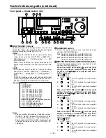
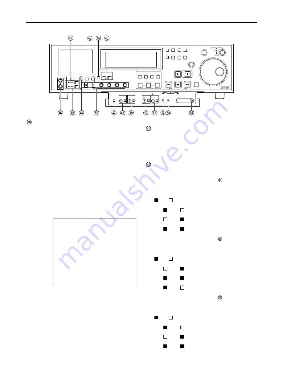
INPUT SELECT buttons
Switch the video and audio input signals. You can also
switch the video input signals to the internal signal
selected at setup menu No. 600 (INT SG).
VIDEO:
Each time the VIDEO button is pressed, the input
video signal switches: [Y PB PR]
→
[CMPST]
→
[SDI](optional)
→
[1394](optional)
→
[SG
(SG/SG1/SG2)].
When SG is selected, the signal switches to the
internal signal selected at setup menu No. 600 (INT
SG).
AUDIO:
Each time the AUDIO button is pressed, the input
audio signal switches: [ANALOG]
→
[AES/EBU]
→
[USER SET]
→
[SDI](optional)
→
[1394](optional)
→
[SG].
USER SET enables you to select and record the input
signals separately on PCM audio signal channels 1
through 4. Use in conjunction with the setup menu.
Example:
Notes:
• You can inhibit input switching (video and audio) of
the INPUT SELECT buttons with setup menus No.
112 (V IN SEL INH) and No. 113 (A IN SEL INH).
• You cannot select SDI and 1394 unless you have
installed the optional board (AJ-YA755G, AJ-
YAD850G).
Settings
AUDIO button
USER SET
Setup menus
No. 715 (CH1 IN SEL): ANA
No. 716 (CH2 IN SEL): DIGI
No. 717 (CH3 IN SEL): DIGI
No. 718 (CH4 IN SEL): ANA
No. 719 (D IN SEL12): AES
No. 720 (D IN SEL34): SIF
PCM audio signals to be recorded on the card
CH1 : Analog input signals
CH2 : AES/EBU digital signals
CH3 : SDI input digital signals
CH4 : Analog input signals
AUDIO MIX switch
Select the audio signals to be recorded to audio
channels CH1/CH2/CH3/CH4.
1&2 :
Switch the input to CH1 with REC CH1/CH3.
Switch the input to CH2 with REC CH2/CH4.
3&4 :
Switch the input to CH3 with REC CH1/CH3.
Switch the input to CH4 with REC CH2/CH4.
REC CH1/CH3 button and REC CH2/CH4 button
Select the audio signals to be recorded to audio
channels CH1/CH2/CH3/CH4.
When the AUDIO MIX switch
is at the [1&2]
setting, the setting is switched by one step in the
sequence of A
→
→
B
→
→
C each time the REC CH1/3
button is pressed.
(
ON; OFF)
CH1/3
CH2/4
A
The CH1 signals are recorded on
CH1.
B
The CH2 signals are recorded on
CH1.
C
The CH1+CH2 signals are recorded
on CH1.
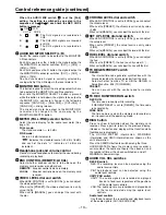
When the AUDIO MIX switch
is at the [1&2]
setting, the setting is switched by one step in the
sequence of A
→
→
B
→
→
C each time the REC CH2/4
button is pressed.
(
ON; OFF)
CH1/3
CH2/4
A
The CH2 signals are recorded on
CH2.
B
The CH1+CH2 signals are recorded
on CH1.
C
The CH1 signals are recorded on
CH2.
When the AUDIO MIX switch
is at the [3&4]
setting, the setting is switched by one step in the
sequence of A
→
→
B
→
→
C each time the REC CH1/3
button is pressed.
(
ON; OFF)
CH1/3
CH2/4
A
The CH3 signals are recorded on
CH3.
B
The CH4 signals are recorded on
CH3.
C
The CH3+CH4 signals are recorded
on CH3.


