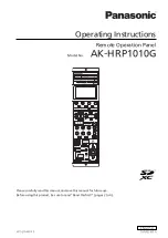
background image

Operating Instructions

Remote Operation Panel

Model No.


AK-HRP1010G

Please carefully read this manual, and save this manual for future use.

Before using this product, be sure to read “Read this first!” (pages 2 to 4)  .

W1021AM0 -PS

DVQP2583ZA

ENGLISH

Summary of Contents for AK-HRP1010G

Page 1: ...ions Remote Operation Panel Model No AK HRP1010G Please carefully read this manual and save this manual for future use Before using this product be sure to read Read this first pages 2 to 4 W1021AM0 PS DVQP2583ZA ENGLISH ...

Page 2: ...es with part 15 of the FCC Rules Operation is subject to the following two conditions 1 This device may not cause harmful interference and 2 this device must accept any interference received including interference that may cause undesired operation FCC Warning To assure continued FCC emission limit compliance follow the attached installation instructions and the user must use only shielded interfa...

Page 3: ...ence if it is being used in an EMC environment such as an area where strong electromagnetic fields are generated by the presence of signal transmission towers cellular phones etc In order to minimize the adverse effects of the interference on the apparatus in cases like this it is recommended that the following steps be taken with the apparatus being affected and with its operating environment 1 P...

Page 4: ...ІЯ ПРО ПІДТВЕРДЖЕННЯ ВІДПОВІДНОСТІ ПРОДУКТУ Виробник Panasonic Corporation Панасонік Корпорейшн Адреса виробника Kadoma Osaka Japan Кадома Осака Японія Країна походження Japan Японія Імпортер ТОВ ПАНАСОНІК УКРАЇНА ЛТД Адреса Імпортера вул Васильківська буд 30 м Київ 03022 Україна Примітки Термін служби виробу 7 років Дату виготовлення можна визначити за комбінацією букв і цифр серійного номера що ...

Page 5: ...lter 39 Displaying and setting the ND filter 39 CC filter 40 Displaying and setting the CC filter 40 Color temperature ECC 41 Setting the color temperature ECC 41 Master gain M GAIN 42 Displaying and setting the master gain M GAIN 42 Shutter SHUTTER 43 Displaying and setting the shutter SHUTTER 43 Master pedestal M PED 44 Displaying and setting the master pedestal M PED 44 Iris IRIS 45 Displaying ...

Page 6: ...SETTING 129 ROP AUTH SETTING 130 Software 131 IP connection 131 IP connection procedure 131 Installing the software 131 Connecting and setting the personal computer 132 Setting the IP addresses of the devices 132 ROP Setup Software 133 Notice about using ROP Setup Software 134 Firewall 134 Reference 135 Connector pin assignment table 135 1 CCU connector 135 2 LAN connector 135 3 PREVIEW connector ...

Page 7: ...shown in the manual s illustrations and screen displays may differ from how it actually appears The screenshots are used in accordance with the guidelines of Microsoft Corporation Abbreviations The following abbreviations are used in this manual The term memory card will be used below as a generic term for both SD SDHC and SDXC memory cards SD SDHC or SDXC will be used in descriptions that refer t...

Page 8: ... a camera control unit AK UCU500 AK UCU600 sold separately Use a dedicated optical fiber multi cable to connect a studio handy camera to a camera control unit and use an ROP cable or IP connection to connect this unit to the camera control unit When IP connections are used up to 99 camera control units can be controlled 8 Introduction ...

Page 9: ... THE PRODUCT ITSELF LOSS OF REGISTERED DATA CAUSED BY ANY FAILURE ANY DAMAGE OR CLAIMS DUE TO LOSS OR LEAKAGE OF IMAGE DATA OR SETTING DATA SAVED ON THIS UNIT OR ON A MEMORY CARD OR PERSONAL COMPUTER Network security This unit also has functions which are used when it is connected to a network Using the unit when it is connected to a network may possibly give rise to the following Leakage or discl...

Page 10: ...erature and humidity Avoid water droplets Avoid static electricity Upgrade software You can obtain the upgrade software from Service and Support on the following website https pro av panasonic net For the upgrade procedure refer to the instructions included with the download file Software for peripheral equipment Software updates will also become necessary for the peripheral equipment that is conn...

Page 11: ...n Eliminate the need for individual ROP cables by connecting up to 99 CCUs via a network hub 100base TX switching hub The unit is equipped with PoE 1 allowing connection to a network device that supports the PoE standard IEEE802 3af com pliant 2 The ROP Setup Software can be used to set the camera connections 1 Power over Ethernet Referred to as PoE in this manual 2 For details on PoE power supply...

Page 12: ...a qualified contractor to dispose of the unit prop erly in order to protect the environment LCD panels The pixels of the LCD panel are controlled to obtain high precision with 99 99 of the effective pixels This leaves less than 0 01 of pixels that may not light or may remain on all the time This is normal and will have no effect on the images you shoot There may be some unevenness on the screen de...

Page 13: ...nit or subjecting it to a strong impact or vibration may cause a failure or accident Do not allow any foreign objects to enter inside the unit Allowing water metal items food or drink or other foreign objects to enter inside the unit may cause a fire or electric shock Installation location This unit is designed for indoor use only Use the unit on a stable and horizontal surface that is sufficientl...

Page 14: ... the screws in a location easily accessible when required The next time you use the rack mount brackets to secure the unit tighten the four screws to a torque of 50 N cm or more Rack installation rack mounting Secure the unit to the rack using two securing screws The securing screws are not supplied with the unit Purchase screws that will fit the φ5 mm 3 16 inch in diameter holes before rack mount...

Page 15: ... the camera to assign to each camera control number under SYSTEM CAM IP SEARCH 3 Set the account information of the connection destination device under SYSTEM CAMERA AUTH SETTING 4 Set the account information of the connection destination device under SYSTEM CAMERA AUTH SETTING Switching between serial connection and IP connection Switch between serial connection and IP connection via the CONNECT ...

Page 16: ...ard in IP connection is loaded in serial connection the operation mode becomes IP connection 2 If an ROP configuration file that was saved to a memory card in serial connection is loaded in IP connection the operation mode becomes serial connection 16 Connection ...

Page 17: ...s possible CCU connections Serial connection ROP cable Connection example AK UCU600 AK HRP1010 1 Connect the CCU connector on this unit to the ROP connector on the CCU using a dedicated ROP cable sold separately 2 When you have finished connecting the equipment turn on the main power of the CCU If a camera is not connected some of the control functions from the unit to the CCU will be limited Turn...

Page 18: ... or higher for the LAN cable 2 Max 100 m 328 1 ft 2 STP shielded twisted pair 2 When you have finished connecting the equipment turn on the power of the CCU If a camera is not connected some of the control functions from the unit to the CCU will be limited Up to 99 CCUs AK UCU500 AK UCU600 can be controlled from the unit To operate CCUs via an IP connection you need to configure the CONNECT SETTIN...

Page 19: ...amera and viewfinder are On Off The viewfinder has been turned off from the unit n On off operation for the viewfinder cannot be performed if the power on the viewfinder is turned off 3 BARS TEST button Use this button to output the CCU color bar signal from the camera video output on the CCU rear panel To select a CCU color bar type select FUNCTION SYSTEM CCU INFO BARS HD or BARS SD in the ROP me...

Page 20: ...to auto black balance adjustment 7 AUTO SET UP button Use this button to start auto setup The setup status is output to the picture monitor PM Auto Setup see page 36 8 CHARA button Use this button to switch on and off the character display of the status screen on the CCU pic ture monitor PM Status displays button press method On short press Displays characters on the picture monitor PM Each short ...

Page 21: ...en FLARE GAMMA KNEE W CLIP HD D UHD D or SD D are assigned to the buttons On OFF Off ON When functions other than the above are assigned On ON Off OFF n Set the function assigned to the ASSIGN button in MAINTENANCE ROP VOL BUTTON ASSIGN BUTTON in the ROP menu ASSIGN BUTTON see page 115 21 Parts and their functions ...

Page 22: ...sing these buttons enables dis ables the functions assigned to each button Set the functions to assign to the CONTROL MODE buttons in MAINTENANCE ROP VOL BUTTON CONTROL1 to CONTROL5 and MODE1 to MODE5 in the ROP menu CONTROL1 to CONTROL5 see page 114 MODE1 to MODE5 see page 115 Status displays When FLARE GAMMA KNEE W CLIP HD D UHD D or SD D are assigned to the buttons On OFF Off ON When functions ...

Page 23: ...revious menu level 4 UNDO button Use this button to restore the values controlled during the setting operation to the values prior to control It is enabled when lit The operation will be applied to the single menu item currently being controlled 5 MENU button Use this button to display the menu screen on the LCD panel Status displays On Menu screen is displayed Off Menu screen is hidden status scr...

Page 24: ...f in sequence with each press of the but ton Status displays On Scene files 6 to 8 can be selected Off Scene files 1 to 5 can be selected 3 1 6 2 7 3 8 4 and 5 buttons SCENE FILE Use these buttons to recall the corresponding scene files as necessary Scene file see page 37 Status displays On A scene file is selected Off A scene file is not selected 4 STORE button Use this button to register scene f...

Page 25: ...the ROP menu STD POSI CC see page 116 5 CC setting buttons Use the up and down buttons to select the CC filter setting When HEAD button off Changes the CC filter setting When HEAD button lit Only displays the CC filter position Switching is not possible CC filter see page 40 When ECC button lit When MAINTENANCE ROP VOL BUTTON ECC BUTTON CTRL is set to VAR in the ROP menu you can configure the ECC ...

Page 26: ...sition set in the ROP menu n The standard position of the master gain can be set in MAINTENANCE ROP VOL BUTTON STD POSI M GAIN in the ROP menu STD POSI M GAIN see page 116 10 M GAIN setting buttons Use the up and down buttons to select the master gain video input sensitivity setting Master gain M GAIN see page 42 11 M GAIN display This displays the combined value of the master gain M GAIN adjustme...

Page 27: ...n or off Status displays On ON Off OFF 3 SYNC button SHUTTER Use this button switch between the shutter and sync shutter Status displays On Sync shutter Off Step shutter 4 SHUTTER setting buttons Use the up and down buttons to select the shutter speed setting Shutter SHUTTER see page 43 27 Parts and their functions ...

Page 28: ...E H D D M A TR IX 1 2 This is a target of the paint control lock PAINT LOCK 3 FLARE button When this button is lit the BLACK R G B dial can be used as a flare R G B adjustment dial When the button is not lit the dial is used as the pedestal R G B adjustment dial Status displays On Flare adjustment Off Pedestal adjustment 4 PAINT LOCK button Lock disable the paint control operations The GAIN R G B ...

Page 29: ... H D D T L P E D R 1 9 0 2 5 3 2 0 0 G B T E M P C A M R C V F 9 9 9 9 C C U R C V G A M M A K N E E H D D M A T R I X 1 2 For the operating procedure see the following page SELECT dial see page 47 8 TEMP indicator This indicator lights when TEMP is selected with the SELECT dial SELECT dial see page 47 9 SYNC indicator This indicator lights when SYNC is selected with the SELECT dial SELECT dial se...

Page 30: ... it right clockwise to increase the master pedestal For details on adjusting the master pedestal see the following page Master pedestal M PED see page 44 5 RELATIVE button Use this button to set whether the variable range of the IRIS lever will be dependent on the SENSE dial and COARSE dial Status displays On The IRIS lever is dependent on the settings of the SENSE dial and COARSE dial Off Sets th...

Page 31: ...s the iris to CLOSE Off Cancels iris CLOSE 11 M PED display This display shows the master pedestal value 12 IRIS LOCK button Use this button to disable lock iris operation Lock range Status displays Off Iris can be controlled Lit Iris operation is disabled locked Flashing Due to iris adjustment from another device the adjustment value and the IRIS lever position do not match n If you adjust the IR...

Page 32: ...urned to the lock position the button turns off and normal control becomes possible n This also flashes if the camera adjustment values and M PED dial position are offset when the control target camera is switched At the point in time when the M PED dial is moved to the position that matches the camera adjustment values the button turns off and normal control becomes possible 32 Parts and their fu...

Page 33: ... The camera cable is connected normally 4 PANEL ACTIVE button Use this button to lock disable the panel operation When disabled the LCD panel display will turn off The ND CC M GAIN and SHUTTER setting buttons will also turn off Lock range Status displays On Enabled Off Disabled 5 CALL button Press this button to call the camera operator The call switch on the camera and CCU is lit while this butto...

Page 34: ...ne files user files and other files to a memory card Memory cards see page 10 8 Memory card access indicator This indicator lights when data is read from or written to a memory card 9 Torque adjustment screw Use a flat bladed screwdriver to adjust the torque of the iris lever 34 Parts and their functions ...

Page 35: ...onnections to the CCU 2 LAN connector Use a LAN cable to connect to a CCU or personal computer that supports IP connections 3 PREVIEW connector This connector outputs preview signals 4 SIGNAL GND terminal Connect this to the system ground 35 Parts and their functions ...

Page 36: ...on A The AUTO SET UP button flashes while the auto setup start preparation mode is established and a square marker appears in the center of the camera viewfinder Align the white at the center of the gray scale with this square marker To cancel setup press and hold this button 2 Press the AUTO SET UP button A again The AUTO SET UP button lights as auto setup starts Holding down the AUTO SET UP butt...

Page 37: ...then the store operation is performed the state at that point in time is stored in the scene file Opening a scene file A B A 1 6 2 7 3 8 4 and 5 buttons B Scene file page switching button Operating procedure 1 Press the desired scene number button A The scene file page can be switched between 1 to 5 and 6 to 8 with the scene file page switching button B The pressed button lights and the scene file...

Page 38: ...t DTL dial D Detail enhancer adjustment C D A B A PAINT LOCK button B GAIN R GAIN G and GAIN B dials C BLACK R BLACK G and BLACK B dials D DTL dial Operating procedure 1 Adjust each item with the control dials 2 Press the PAINT LOCK button A The button lights 3 Turn the control dial to its center position 4 Press the PAINT LOCK button A again The button turns off The value of the adjustment positi...

Page 39: ...ard pos ition remains set while the indicator is green lit STD POSI ND see page 116 D A B C A ND indicator B ND display C ND setting buttons D HEAD button Operating procedure 1 Press the ND setting buttons C This allows you to change the ND filter setting value The setting cannot be changed while the HEAD button D is lit Only position display is performed The HEAD button also lights when operating...

Page 40: ...The standard pos ition remains set while the indicator is green lit STD POSI CC see page 116 A B C A CC indicator B CC display C CC setting buttons Operating procedure 1 Press the CC setting buttons C This allows you to change the CC filter setting value The setting cannot be changed while the HEAD button is lit Only position display is performed The HEAD button also lights when operating from the...

Page 41: ...tton is lit the ECC function is enabled The function is disabled when the button is unlit When you set SCENE to be displayed on the status screen you can verify the ECC setting C ヤ ヰ G A I N G A I N R 1 0 0 0 3 1 6 G B U H D D T L P E D R 1 9 0 2 5 3 2 0 0 G B T E M P F 9 9 9 9 S C E N E 1 N D 2 C C A E C C 1 5 0 0 0 K S H T 1 1 0 0 G A M M A K N E E H D D M A T R I X 1 2 C 2 Press the CC setting ...

Page 42: ...s orange lit The standard position remains set while the indicator is green lit STD POSI M GAIN see page 116 D A B C A M GAIN indicator B M GAIN display C M GAIN setting buttons D VAR button Operating procedure 1 Press the M GAIN setting buttons C This allows you to change the master gain setting value When the VAR button D is pressed to turn on the button the master gain can make fine adjustments...

Page 43: ...ch between step and sync shutter The current setting value is displayed in the SHUTTER display B B A D C A ON button SHUTTER B SHUTTER display C SHUTTER setting buttons D SYNC button SHUTTER Operating procedure 1 Press the ON button SHUTTER A to turn on the button The shutter is enabled To adjust the sync shutter press the SYNC button SHUTTER D to turn on the button 2 Press the SHUTTER setting but...

Page 44: ...played on the M PED display A when the M PED dial B is operated Adjustment is possible while the M PED LOCK button C is off canceled C A B A M PED display B M PED dial C M PED LOCK button Operating procedure 1 Turn the M PED dial B The setting value is displayed on the M PED display A 44 Adjustment and settings ...

Page 45: ...ial Operating procedure 1 Adjust the iris level with the IRIS lever B Moving it forward adjusts the level in the CLOSE direction and moving it backward adjusts the level in the OPEN direction Use the SENSE dial G to adjust the iris variable range when the IRIS lever B is moved from the center to the upper and lower edges SENSE dial see page 30 Use the COARSE dial H to adjust the iris value when th...

Page 46: ...on the button The auto iris turns on When the auto iris is on the convergence level of the iris can be adjusted with the IRIS lever B Moving it forward adjusts the level in the CLOSE direction and moving it backward adjusts the level in the OPEN direction 46 Adjustment and settings ...

Page 47: ...rol via the unit can be selected with the dial Camera selection see page 48 USER adjusts the function set with MAINTENANCE ROP VOL BUTTON USER ASSIGN in the ROP menu B F E D A C A SELECT dial B TEMP indicator C CAM SEL indicator D SYNC indicator E USER indicator F MFLR indicator Operating procedure 1 Press the SELECT dial A for at least approximately 1 second This allows you to select TEMP CAM SEL...

Page 48: ...lect TEMP CAM SEL SYNC USER and MFLR 2 Turn the SELECT dial A to select CAM SEL Turn the dial until the CAM SEL indicator B lights 3 Press the SELECT dial A The mode changes to camera selection mode 4 Turn the SELECT dial A to select the camera Turning the dial changes the camera number displayed on the status screen 5 Press the SELECT dial A The camera selection is confirmed and the camera with t...

Page 49: ... both sides of the status screen changes the page of the status screen When the ROP menu is displayed pressing the EXIT button closes the ROP menu and switches to the status screen ヤ ヰ 1 P A IN T 3 M A IN TE N A N C E 2 FU N C TION 4 S Y S TE M C 0 1 A K U C 4 0 0 0 M E N U Transitioning from the MENU screen Press the EXIT button to transition G AI N GAIN R 10 0 0 31 6 G B U HD D TL P ED R 19 0 25...

Page 50: ...on the camera side CCU RCV Displays the optical transmission reception strength on the CCU side CAM INFO This displays the camera information ヤ ヰ G A I N G A I N R 1 0 0 0 3 1 6 G B U H D D T L P E D R 1 9 0 2 5 3 2 0 0 G B T E M P F 9 9 9 9 C 0 1 A K U C 4 0 0 0 U H D 5 9 9 4 2 1 6 0 5 9 9 4 p G A M M A K N E E H D D M A T R I X 1 2 Display Item C Displays the name of the currently selected camer...

Page 51: ...red from the CCU CC filter see page 40 ECC Displays the current information of ECC COLOR TEMP in the ROP menu Color temperature ECC see page 41 SHT Displays the currently set shutter value Shutter SHUTTER see page 43 ASSIGN This displays the ASSIGN information ヤ ヰ G A I N G A I N R 1 0 0 0 3 1 6 G B U H D D T L P E D R 1 9 0 2 5 3 2 0 0 G B T E M P F 9 9 9 9 G L I N T D R S O N G A M M A K N E E H...

Page 52: ...in MAINTENANCE ROP SETTING SETTING LOAD can be checked on the LCD panel Press the ASSIGN STATUS button A to display the assignments ヤ ヰ GAIN U CHRM GAIN F9999 GAMMA KNEE HD D MATRIX 1 2 FLARE ON GAMMA ON KNEE ON W CLIP ON U DTL ON 2 2 ASSIGN BUTTON USER ASSIGN SETTING A B A ASSIGN STATUS button B Buttons 1 to 5 52 Status screen ...

Page 53: ...T E N A N C E 2 F U N C T I O N 4 S Y S T E M C 0 1 A K U C 4 0 0 0 M E N U A C B A MENU button B LCD panel C EXIT button Operating procedure 1 Press the MENU button A The ROP menu appears on the LCD panel B Pressing the EXIT button C returns you to the status screen 2 Press the menu item you wish to set You can select from the following menu items For the menu operating procedures see the followi...

Page 54: ... shows the example of PAINT SW C 0 1 A K U C 4 0 0 0 P A IN T PA IN T SW B LA C K SH U TTER PED ESTA L U H D C H R OM A H D C H R OM A 1 5 C 0 1 A K U C 4 0 0 0 P A IN T S W WHITE SHADING BLACK SHADING ON ON OFF ON ON OFF ON ON OFF ON ON OFF 1 2 FLARE GAMMA D R S BLACK GAMMA WHITE CLIP KNEE COLOR CORRECT MATRIX HD SKIN TONE DTL UHS SKIN TONE DTL 4 Press or on the right side to scroll through the p...

Page 55: ...F ON ON OFF 1 2 FLARE GAMMA DRS BLACK GAMMA WHITE CLIP KNEE COLOR CORRECT MATRIX HD SKIN TONE DTL UHS SKIN TONE DTL C D C MENU dial D UNDO button Other menu operations Returning to the menu selection screen 1 Press the EXIT button E This returns you to the previous screen C 0 1 A K U C 4 0 0 0 PA IN T PA IN T SW B LA C K SH U TTER PED ESTA L U H D C H R OM A H D C H R OM A 1 5 C 0 1 A K U C 4 0 0 ...

Page 56: ... SYNCHRO SYNCHRO see page 70 MODE MODE see page 70 SW SW see page 70 BLACK SHADING H SAW R H SAW R see page 71 H SAW G H SAW G see page 71 H SAW B H SAW B see page 71 H PARA R H PARA R see page 71 H PARA G H PARA G see page 71 H PARA B H PARA B see page 71 V SAW R V SAW R see page 71 V SAW G V SAW G see page 71 V SAW B V SAW B see page 71 V PARA R V PARA R see page 71 V PARA G V PARA G see page 71...

Page 57: ...e 77 G AXIS INFO G AXIS INFO see page 77 B GAIN INFO B GAIN INFO see page 77 C TEMP INFO C TEMP INFO see page 77 CAM USER SW TEMP R GAIN R GAIN see page 78 G AXIS G AXIS see page 78 B GAIN B GAIN see page 78 COLOR TEMP COLOR TEMP see page 78 WHITE SHADING H SAW R H SAW R see page 79 H SAW G H SAW G see page 79 H SAW B H SAW B see page 79 H PARA R H PARA R see page 79 H PARA G H PARA G see page 79 ...

Page 58: ...3 SLOPE R SLOPE R see page 83 SLOPE B SLOPE B see page 83 SLOPE MASTER SLOPE MASTER see page 83 SW SW see page 83 WHITE CLIP LEVEL R LEVEL R see page 84 LEVEL B LEVEL B see page 84 LEVEL MASTER LEVEL MASTER see page 84 HI COLOR LEVEL HI COLOR LEVEL see page 84 SW SW see page 84 HI COLOR SW HI COLOR SW see page 84 DRS EFFECT DEPTH EFFECT DEPTH see page 85 SW SW see page 85 UHD DTL M DTL M DTL see p...

Page 59: ...W DRK DTL SW see page 87 SD DTL H DTL LEVEL H DTL LEVEL see page 88 V DTL LEVEL V DTL LEVEL see page 88 PEAK1 FRQ PEAK1 FRQ see page 88 PEAK2 FRQ PEAK2 FRQ see page 88 CRISP CRISP see page 88 LEVEL DEPEND LEVEL DEPEND see page 88 DARK DTL DARK DTL see page 88 SW SW see page 88 UHD SKIN TONE DTL MEMORY SELECT MEMORY SELECT see page 89 CURSOR CURSOR see page 89 H POS H POS see page 89 V POS V POS se...

Page 60: ... Q PHASE Q PHASE see page 90 SW SW see page 90 LINEAR MATRIX PRESET MATRIX PRESET MATRIX see page 91 LINEAR TABLE LINEAR TABLE see page 91 COLOR CORRECT COLOR CORRECT see page 91 R G P R G P see page 91 R G N R G N see page 91 R B P R B P see page 91 R B N R B N see page 91 G R P G R P see page 91 G R N G R N see page 91 G B P G B P see page 91 G B N G B N see page 91 B R P B R P see page 91 B R N...

Page 61: ...e 93 SAT B SAT B see page 93 PHASE B PHASE B see page 93 SAT B_MG SAT B_MG see page 93 PHASE B_MG PHASE B_MG see page 93 SAT MG SAT MG see page 93 PHASE MG PHASE MG see page 93 SAT MG_R SAT MG_R see page 93 PHASE MG_R PHASE MG_R see page 93 SAT R SAT R see page 93 PHASE R PHASE R see page 93 SAT R_YE SAT R_YE see page 93 PHASE R_YE PHASE R_YE see page 93 SAT YE SAT YE see page 93 PHASE YE PHASE YE...

Page 62: ... page 96 DNR LEVEL DNR LEVEL see page 96 DNR SW DNR SW see page 96 SDR CONV GAIN SDR CONV GAIN see page 96 SDR CONV CLIP SDR CONV CLIP see page 96 SDR CONV BLACK SDR CONV BLACK see page 96 SDR CONV POINT SDR CONV POINT see page 96 SDR CONV SLOPE SDR CONV SLOPE see page 97 NON LINEAR MATRIX R G P R G P see page 98 R G N R G N see page 98 R B P R B P see page 98 R B N R B N see page 98 G R P G R P s...

Page 63: ...e page 100 PHASE Mg B B PHASE Mg B B see page 100 SAT B SAT B see page 100 PHASE B PHASE B see page 100 SAT B B Cy SAT B B Cy see page 100 PHASE B B Cy PHASE B B Cy see page 100 SAT B Cy SAT B Cy see page 100 PHASE B Cy PHASE B Cy see page 100 SAT B Cy Cy SAT B Cy Cy see page 100 PHASE B Cy Cy PHASE B Cy Cy see page 100 SAT Cy SAT Cy see page 100 PHASE Cy PHASE Cy see page 100 SAT Cy Cy G SAT Cy C...

Page 64: ...GAIN see page 102 MIC1 LINE LV MIC1 LINE LV see page 102 MIC1 AMP MIC1 AMP see page 102 MIC2 GAIN MIC2 GAIN see page 102 MIC2 LINE LV MIC2 LINE LV see page 102 MIC2 AMP MIC2 AMP see page 102 SHOOTING MODE SHOOTING MODE see page 102 CAM FAN CAM FAN see page 102 HDR SW HDR SW see page 102 TALLY GUARD TALLY GUARD see page 103 ASU FILTER ASU FILTER see page 103 ASU MODE ASU MODE see page 103 ASU M PED...

Page 65: ...age 105 SD HD V SD HD V see page 105 SCH SCH see page 105 CABLE CONNECT CABLE CONNECT see page 105 AUTO IRIS SETTING WINDOW SELECT WINDOW SELECT see page 106 PEAK RATIO PEAK RATIO see page 106 IRIS GAIN IRIS GAIN see page 106 IRIS SPEED IRIS SPEED see page 106 IRIS LEVEL IRIS LEVEL see page 106 IRIS RANG IRIS RANG see page 106 LENS EXT COMP SW LENS EXT COMP SW see page 106 LENS EXT COMP LV LENS EX...

Page 66: ...V SAW R W V SAW R see page 110 W V SAW G W V SAW G see page 110 W V SAW B W V SAW B see page 110 W V PAR R W V PAR R see page 110 W V PAR G W V PAR G see page 110 W V PAR B W V PAR B see page 110 STORE NUM STORE NUM see page 110 STORE STORE see page 110 CANCEL CANCEL see page 110 MONITOR R R see page 111 G G see page 111 B B see page 111 SEQ SEQ see page 111 ENC ENC see page 111 REFERENCE REF CALL...

Page 67: ...ge 116 STD POSI CC STD POSI CC see page 116 IRIS LEVER SETTING LEVER MODE LEVER MODE see page 117 PRIORITY PRIORITY see page 117 RELATIVE MODE RELATIVE MODE see page 117 CALIB TOP CALIB TOP see page 117 CALIB BOTTOM CALIB BOTTOM see page 117 ROP SETTING LCD BRIGHT LCD BRIGHT see page 118 LED BRIGHT LED BRIGHT see page 118 7SEG 1 BRIGHT 7SEG 1 BRIGHT see page 118 7SEG 2 BRIGHT 7SEG 2 BRIGHT see pag...

Page 68: ...AC ADDRESS see page 125 SAVE SAVE see page 125 CAM IP SEARCH CAM IP SEARCH CAM IP SEARCH see page 126 SAVE SAVE see page 126 HIT HIT see page 126 CAM No CAM No see page 126 MANUAL IP SETTING CAM No SELECT CAM No SELECT see page 127 CAM IP CAM IP see page 127 PORT PORT see page 127 SAVE SAVE see page 127 CONNECT SETTING CAM No SELECT CAM No SELECT see page 128 CONNECT MODE CONNECT MODE see page 128...

Page 69: ...Enables or disables white shading sawtooth waveform or parabolic waveform FLARE Enables or disables the flare GAMMA Enables or disables the gamma BLACK GAMMA Enables or disables the black gamma DRS Enables or disables the dynamic range stretcher function When this is enabled contrast is adjusted automatically WHITE CLIP Enables or disables the white clip function KNEE Enables or disables the knee ...

Page 70: ...U to be connected C 0 1 A K U C 4 0 0 0 S H U TTE R SYNCHRO SPEED 1 1 MODE SW SHUT OFF 61 7 48 Item Setting details SPEED Sets the shutter speed for when MODE is set to SHUT SYNCHRO Sets the shutter speed for when MODE is set to SYNC MODE Selects the shutter operation mode SHUT The shutter speed set in SPEED is used SYNC The shutter speed set in SYNCHRO is used SW Enables or disables the shutter f...

Page 71: ...V PARA B CORRECT SW ON Item Setting details H SAW R Adjusts the black shading gain for R G and Bch in the horizontal direction using a sawtooth waveform H SAW G H SAW B H PARA R Adjusts the black shading gain for R G and Bch in the horizontal direction using a parabolic waveform H PARA G H PARA B V SAW R Adjusts the black shading gain for R G and Bch in the vertical direction using a sawtooth wave...

Page 72: ...PED OFFSET M PED RANGE OFF OFF WIDE Item Setting details R PED Sets the red correction level for the master pedestal G PED Sets the green correction level for the master pedestal B PED Sets the blue correction level for the master pedestal M PED Indicates set master pedestal value M PED ABS DISP Sets the master pedestal display setting PED OFFSET Sets whether to retain the Rch Gch and Bch pedestal...

Page 73: ...rmed for the CCU The setting values will vary also depending on the connected camera Items with the function disabled are indicated by For details on each setting item check also the operating instructions of the camera and CCU to be connected C 0 1 A K U C 4 0 0 0 U H D C H R OM A LEVEL 1 1 LEVEL SW OFF 0 Item Setting details LEVEL Adjusts the chroma gain LEVEL SW Enables or disables the chroma g...

Page 74: ...or the CCU Otherwise the control is performed for the camera The setting values will vary also depending on the connected camera Items with the function disabled are indicated by For details on each setting item check also the operating instructions of the camera and CCU to be connected C 0 1 A K U C 4 0 0 0 H D C H R OMA LEVEL 1 1 LEVEL SW OFF 0 Item Setting details LEVEL Adjusts the chroma gain ...

Page 75: ...g details R GAIN Sets the red correction level for the gain G GAIN Sets the green correction level for the gain B GAIN Sets the blue correction level for the gain GAIN OFFSET Sets whether to retain the Rch Gch and Bch gain levels when the auto white balance is adjus ted GAIN ABS Sets whether to display the absolute value for the RGB gain When this is set to ON and the R GAIN G GAIN B GAIN values a...

Page 76: ...uctions of the camera and CCU to be connected C 0 1 A K U C 4 0 0 0 C OLOR TEM P 1 1 0 0 3200 0 G AXIS R GAIN B GAIN COLOR TEMP Item Setting details R GAIN Sets the red correction level for the color temperature G AXIS Sets the green correction level for the color temperature B GAIN Sets the blue correction level for the color temperature COLOR TEMP Set color temperature settings 76 ROP menu ...

Page 77: ...P Sets the color temperature when COLOR TEMP SW is set to ON An arrow will appear on the right if the value is too high or low COLOR TEMP SW Turn this on when adjusting the color temperature manually PRI MEM push Stores the C TEMP INFO R GAIN G AXIS and B GAIN setting values to the five ROP memories A to E They can be recalled by assigning them in ROP VOL BUTTON MODE1 to MODE5 They are unset by de...

Page 78: ...C 4 0 0 0 C A M U S E R S W TE MP 1 1 0 0 3200 0 G AXIS R GAIN B GAIN COLOR TEMP Item Setting details R GAIN Sets the red correction level for the color temperature G AXIS Sets the green correction level for the color temperature B GAIN Sets the blue correction level for the color temperature COLOR TEMP Sets the color temperature for when C TEMP is assigned to the USER 1 USER 2 USER 3 or USER 4 bu...

Page 79: ...PARA B ON CORRECT SW Item Setting details H SAW R Adjusts the white shading gain for R G and Bch in the horizontal direction using a sawtooth waveform H SAW G H SAW B H PARA R Adjusts the white shading gain for R G and Bch in the horizontal direction using a parabolic waveform H PARA G H PARA B V SAW R Adjusts the white shading gain for R G and Bch in the vertical direction using a sawtooth wavefo...

Page 80: ...tem check also the operating instructions of the camera and CCU to be connected FLA R E C 0 1 A K U C 4 0 0 0 1 1 0 0 0 0 G FLARE R FLARE B FLARE ON SW M FLARE Item Setting details R FLARE Adjusts the Rch flare G FLARE Adjusts the Gch flare B FLARE Adjusts the Bch flare M FLARE Adjusts the master flare SW Enables or disables flare correction 80 ROP menu ...

Page 81: ...e master gamma M GAMMA Adjusts the gamma characteristic GAMMA MODE Sets the gamma characteristic type INITIAL GAMMA Sets the rising slope for the gamma BLACK STRCH LV Sets the gamma stretch position for when GAMMA MODE is set to FILM REC DYNAMIC LEVEL Sets the dynamic range for when GAMMA MODE is set to FILM REC KNEE POINT Sets the knee point for when GAMMA MODE is set to VIDEO REC KNEE SLOPE Sets...

Page 82: ...ER B GAMMA SW OFF C 0 1 A K U C 4 0 0 0 B LA C K GA M M A 1 1 B GAMMA B B GAMMA R 0 0 0 Item Setting details B GAMMA R Adjusts the red gamma characteristic near black for the master gamma B GAMMA B Adjusts the blue gamma characteristic near black for the master gamma MASTER B GAMMA Adjusts the gamma characteristic near black SW Enables or disables the black gamma This setting is not available when...

Page 83: ... N EE 1 1 0 00 95 00 0 0 130 0 00 POINT B POINT R POINT MASTER SLOPE MASTER OFF SLOPE B SLOPE R SW Item Setting details POINT R Adjusts the red knee point for POINT MASTER POINT B Adjusts the blue knee point for POINT MASTER POINT MASTER Sets the knee point position SLOPE R Adjusts the red knee slope for SLOPE MASTER SLOPE B Adjusts the blue knee slope for SLOPE MASTER SLOPE MASTER Set the knee sl...

Page 84: ... 0 0 WH ITE C LIP 1 1 0 109 32 0 LEVEL B LEVEL R LEVEL MASTER HI COLOR LEVEL HI COLOR SW OFF SW OFF Item Setting details LEVEL R Adjusts red for LEVEL MASTER LEVEL B Adjusts blue for LEVEL MASTER LEVEL MASTER Set the white clip level HI COLOR LEVEL Sets the level for the mode that expands dynamic range for colors SW Enables or disables the white clip function HI COLOR SW Sets whether to improve co...

Page 85: ...a and CCU to be connected C 0 1 A K U C 4 0 0 0 D R S 1 1 EFFECT DEPTH OFF SW 5 Item Setting details EFFECT DEPTH Sets the compression level for high brightness areas of the dynamic range stretcher function Higher values increase the compression level for high brightness areas SW Enables or disables the dynamic range stretcher function When this is enabled contrast is adjusted auto matically 85 RO...

Page 86: ...m Setting details M DTL Adjusts the level of master detail H DTL LEVEL Adjusts the level of horizontal detail V DTL LEVEL Adjusts the level of vertical detail PEAK FRQ Selects the contour correction frequency band boost frequency or peak frequency Changes the contour width CRISP Set the noise elimination level for the detail signals CLIP Adjusts detail clipping to minimize scintillation resulting ...

Page 87: ...TL SW DRK DTL SW Item Setting details M DTL Adjusts the level of master detail H DTL LEVEL Adjusts the level of horizontal detail V DTL LEVEL Adjusts the level of vertical detail PEAK FRQ Sets the peak frequency for the horizontal detail V DTL FRQ Set the V DETAIL frequency CRISP Set the noise elimination level for the detail signals LEVEL DEPEND Set the level of dark detail removal DARK DTL Set t...

Page 88: ...to be connected OFF ON C 0 1 A K U C 4 0 0 0 S D D TL V DTL LEVEL H DTL LEVEL 4 09 25 15 0 0 0 1 1 PEAK1 FRQ PEAK2 FRQ LEVEL DEPEND CRISP DARK DTL SW Item Setting details H DTL LEVEL Adjusts the level of horizontal detail V DTL LEVEL Adjusts the level of vertical detail PEAK1 FRQ Selects the contour correction frequency band boost frequency or peak frequency Changes the contour width PEAK2 FRQ Sel...

Page 89: ... CURSOR Enables or disables the position cursor that obtains the saturation and color phase information for controlling skin tone detail effects H POS Sets horizontal cursor position V POS Sets vertical cursor position SKIN GET Automatically acquire saturation and hue information from the cursor position ZEBRA SW Sets whether to add a zebra pattern to the Y signals of the PM output to make areas s...

Page 90: ...values CRISP PHASE WIDTH and SATURATION CURSOR Enables or disables the position cursor that obtains the saturation and color phase information for controlling skin tone detail effects H POS Sets horizontal cursor position V POS Sets vertical cursor position SKIN GET Automatically acquire saturation and hue information from the cursor position ZEBRA SW Sets whether to add a zebra pattern to the Y s...

Page 91: ...IX 0 0 0 0 Item Setting details PRESET MATRIX Sets the preset matrix LINEAR TABLE Selects the linear matrix table COLOR CORRECT Selects the color correction table R G P Adjusts the linear matrix between red and green R G N R B P Adjusts the linear matrix between red and blue R B N G R P Adjusts the linear matrix between green and red G R N G B P Adjusts the linear matrix between green and blue G B...

Page 92: ...HASE B_MG 0 0 0 0 0 0 0 0 0 0 0 0 C 0 1 A K U C 4 0 0 0 C OLOR C OR R E C TION PHASE MG SAT MG 3 4 SAT MG_R PHASE MG_R PHASE R SAT R SAT R_YE PHASE R_YE PHASE YE SAT YE SAT YE_G PHASE YE_G C 0 1 A K U C 4 0 0 0 C OLOR C OR R E C TION COLOR CORRECT MATRIX SW OFF OFF OFF 4 4 LINEAR MATRIX Item Setting details PRESET MATRIX Sets the preset matrix LINEAR TABLE Selects the linear matrix table COLOR COR...

Page 93: ... SAT B_MG Adjusts the color saturation between blue and magenta PHASE B_MG Adjusts the color phase between blue and magenta SAT MG Adjusts the color saturation of magenta PHASE MG Adjusts the color phase of magenta SAT MG_R Adjusts the color saturation between magenta and red PHASE MG_R Adjusts the color phase between magenta and red SAT R Adjusts the color saturation of red PHASE R Adjusts the co...

Page 94: ...o the operating instructions of the camera and CCU to be connected C 0 1 A K U C 4 0 0 0 S K IN C OR R E C TION TONE HUE SW TABLE 0 0 A OFF 1 1 Item Setting details HUE Finely adjusts the hue of the skin area TONE Finely adjusts the tone of the skin area TABLE Selects the skin area table SW Enables or disables the fine adjustment function for near skin tone color 94 ROP menu ...

Page 95: ...led are indicated by For details on each setting item check also the operating instructions of the camera and CCU to be connected C 0 1 A K U C 4 0 0 0 D N R LEVEL 3 ON 1 1 SW Item Setting details LEVEL Sets the level for the noise reduction SW Enables disables the noise reduction function 95 ROP menu ...

Page 96: ...s R HLG B GAMMA Adjusts the red gamma characteristic near black for the master gamma B HLG B GAMMA Adjusts the blue gamma characteristic near black for the master gamma M HLG B GAMMA Adjusts the gamma characteristic near black HLG KNEE POINT Sets the knee point for when GAMMA MODE is set to VIDEO REC HLG KNEE SLOPE Sets the knee slope for when GAMMA MODE is set to VIDEO REC HLG B GAMMA Enables or ...

Page 97: ...Item Setting details SDR CONV SLOPE Sets the SDR slope 97 ROP menu ...

Page 98: ...0 0 0 0 0 0 0 0 0 0 1 2 G R N G R P G B P B R N B R P B G P B G N C 0 1 A K U C 4 0 0 0 N ON LIN EA R M A TR IX 2 2 OFF SW Item Setting details R G P Adjusts the matrix between red and green R G N R B P Adjusts the matrix between red and blue R B N G R P Adjusts the matrix between green and red G R N G B P Adjusts the matrix between green and blue G B N B R P Adjusts the matrix between blue and re...

Page 99: ...PHASE Mg SAT Mg SAT Mg Mg B PHASE Mg Mg B PHASE Mg B SAT Mg B SAT Mg B B PHASE Mg B B PHASE B SAT B SAT B B Cy PHASE B B Cy 0 0 0 0 0 0 0 0 0 0 0 0 C 0 1 A K U C 4 0 0 0 C OLOR A D J U S TME N T PHASE B Cy SAT B Cy SAT B Cy Cy PHASE B Cy Cy 3 5 PHASE Cy SAT Cy SAT Cy Cy G PHASE Cy Cy G PHASE Cy G SAT Cy G SAT Cy G G PHASE Cy G G 0 0 0 0 0 0 0 0 0 0 0 0 C 0 1 A K U C 4 0 0 0 4 5 C OLOR A D J U S TM...

Page 100: ...B B Cy Adjusts the color phase between blue and color between blue and cyan SAT B Cy Adjusts the color saturation between blue and cyan PHASE B Cy Adjusts the color phase between blue and cyan SAT B Cy Cy Adjusts the color saturation between color between blue and cyan and cyan PHASE B Cy Cy Adjusts the color phase between color between blue and cyan and cyan SAT Cy Adjusts the color saturation of...

Page 101: ...SE Yl R Adjusts the color phase between yellow and red SAT Yl R R Adjusts the color saturation between color between yellow and red and red PHASE Yl R R Adjusts the color phase between color between yellow and red and red SW Enables or disables the color adjustment function 101 ROP menu ...

Page 102: ...TRY OFF FCTRY CAM1 HYBRID OFF Mode2 SELECT 3 3 CABLE CONNCT CTRL ROTATION TALLY INPUT TALLY CONTROL TALLY SIGNAL TALLY CONT MD Item Setting details FORMAT Set the camera format When the unit is connected to a CCU this item is only displayed and cannot be changed TALK OFF INCOM1 Sets TALK for INCOM1 to OFF TALK OFF INCOM2 Sets TALK for INCOM2 to OFF MIC1 GAIN Makes coarse adjustments of the MIC1 ga...

Page 103: ...fer to the operating instructions of the camera TALLY CONTROL Sets whether or not to notify the camera when there is a tally input from the PREVIEW con nector When this is set to ON notification is sent if there is tally input when the camera set in TALLY INPUT is selected this function is disabled when connected with a studio camera This is enabled when other than Serial and LAN is set in CONNECT...

Page 104: ...at that is output from the CCU The CCU specifies the format to the camera based on the format selected here CAMERA NUM Changes the camera number controlled by the CCU D C MODE Selects the down conversion system for video output from SD SDI and VBS U C MODE Selects the video up conversion system used for SD SDI and VBS return videos RETURN FS Set the delay mode for the HD return signals RETURN1 SEL...

Page 105: ...E phase used with GL SD REF SD HD V Set the vertical phase used with down convert SD REF SCH Adjust the SCH phase of VBS output CABLE CONNECT Displays the camera connection cable setting You can change the setting via menu operations on the CCU itself HYBRID Indicates that the camera is connected via an optical fiber multi cable FIBER Indicates that the camera is connected via an optical fiber cab...

Page 106: ...SELECT Set the photometry range PEAK RATIO Set the ratio between the peak value and average value for auto iris photometry IRIS GAIN Switch between adjusting the auto iris photometry speed via the iris gain volume or via menu operations Set this to LENS under normal circumstances and adjust using the lens iris volume IRIS SPEED Set the auto iris speed IRIS LEVEL Adjusts the target value brightness...

Page 107: ...S C ON TR OL FOCUS SPEED FOCUS OFF CONTROL SW 1 1 Item Setting details FOCUS Adjusts the lens focus manually FOCUS SPEED Adjusts the focus operation speed ZOOM Adjusts the lens zoom manually ZOOM SPEED Adjusts the zoom operation speed CONTROL SW Enables or disables control of the lens from the unit When this is set to OFF control the lens from the camera 107 ROP menu ...

Page 108: ... of the camera and CCU to be connected C 0 1 A K U C 4 0 0 0 S H U TTE R S E LE C T POSI 2 POSI 1 DISABLE 1 1 SHUT OFF 250 POSI 3 POSI 4 POSI 6 POSI 5 POSI 7 POSI 8 2000 125 1500 120 1000 48 500 Item Setting details POSI1 Sets the shutter speed for POSI 1 to POSI 8 POSI2 POSI3 POSI4 POSI5 POSI6 POSI7 POSI8 SHUT OFF Selects whether to include shutter OFF when switching the shutter position 108 ROP ...

Page 109: ...0 0 LE N S FILE E D IT FILE NUM EXTENDER 2 4 0 0 0 G FRARE R FRARE B FRARE FILE NAME C 0 1 A K U C 4 0 0 0 LE N S FILE E D IT 0 0 0 0 0 0 0 0 3 4 B GAIN W H SAW G W H SAW R W H SAW B W H PAR G W H PAR R W H PAR B R GAIN C 0 1 A K U C 4 0 0 0 LE N S FILE E D IT 0 0 0 0 0 0 NO 1 NO 4 4 W V SAW G W V SAW R W V SAW B W V PAR G W V PAR R W V PAR B STORE STORE NUM CANCEL Item Setting details MODE Saves ...

Page 110: ...re of the display data B FLARE Adjusts the B flare of the display data R GAIN Adjusts the R gain of the display data B GAIN Adjusts the B gain of the display data W H SAW R Adjusts the R G and Bch white shading of the display data in the horizontal direction using a sawtooth wave form W H SAW G W H SAW B W H PAR R Adjusts the R G and Bch white shading of the display data in the horizontal directio...

Page 111: ...g item check also the operating instructions of the camera and CCU to be connected C 0 1 A K U C 4 0 0 0 M ON ITOR 1 1 G R ENC SEQ B OFF OFF OFF ON OFF Item Setting details R Turns the R monitor on or off G Turns the G monitor on or off B Turns the B monitor on or off SEQ Turns the SEQ monitor on or off ENC Turns the ENC monitor on or off 111 ROP menu ...

Page 112: ...Setting value Setting details REF CALL push FCTRY USER1 to USER3 REF1 to REF3 Recalls the reference setting information factory file user file and reference file STORE REF USER1 to USER3 REF1 to REF3 Overwrite the current setting values to the selected file STORE EXEC Execute saving of the reference file 112 ROP menu ...

Page 113: ... OFF 1 1 CCU MENU CURSOR CCU MENU SW CCU MENU EXECUTE ___ indicates factory default settings Item Setting value Setting details CAM MENU SW OFF ON Turns the menu on or off CAM MENU CURSOR Moves the menu cursor or changes setting values CAM MENU EXECUTE Executes the selected process CCU MENU SW OFF ON Turns the menu on or off CCU MENU CURSOR Moves the menu cursor or changes setting values CCU MENU ...

Page 114: ...MTRX CLR A A IRIS S SEL REF CAM_MN Sets the functions to assign to buttons 1 to 5 CONTROL MODE The setting values represent the following menu names PNT S PAINT SWITCH SHUT SHUTTER SPEED B SHD BLACK SHADING PED PEDESTAL H CHRM HD CHROMA U CHRM UHD CHROMA GAIN RB GAIN TEMP COLOR TEMP ECC ECC TEMP U CAM USER SW TEMP W SHD WHITE SHADING FLARE FLARE GAMMA GAMMA B GAM BLACK GAMMA KNEE KNEE W CLIP WHITE...

Page 115: ... on and sets the color temperature to 5600K ECC A to E Sets the color temperature stored to memory in the ECC menu SD D SD DTL HDR K HLG KNEE D EXT2 USER ASSIGN GAIN M GAMM U CHRM H CHRM DRS KNEE S U S DTL H S DTL S HUE S TONE Sets the function to assign to USER of the SELECT dial The setting values represent the following functions GAIN GAIN Operates the R G and B gain values simultaneously This ...

Page 116: ...M 1000 control range of ROP is 256 BLACK Range of CAM 800 control range of ROP is 128 FLARE Range of CAM 200 control range of ROP is 64 The setting parameters are as follows STD R G B Gain 256 BLACK 128 FLARE 64 MODE1 About half the control range of STD MODE2 About one third the control range of STD STD POSI M GAIN 6 to 0 to 36 Sets the standard position of the master gain M GAIN STD POSI VAR 2 9 ...

Page 117: ...oes not match the ROP s IRIS lever position the ROP s IRIS lever position during serial connection will be the basis of operation LAN If the camera s iris position does not match the ROP s IRIS lever position the ROP s IRIS lever position during IP connection will be the basis of operation BOTH When there is either a serial or LAN connection operation from the IRIS lever has priority RELATIVE MODE...

Page 118: ...sec off 500 msec lit repeatedly CALL CYCLE 0 3 to 1 0 PC_LINK ENABLE DISABLE Sets whether to allow communication with ROP Setup Software ENABLE Allows communication This cannot be selected when an account is not registered in ROP AUTH SETTING DISABLE Does not allow communication NOTE Set this to DISABLE when there will be no communication with ROP Setup Software SETTING STORE NO SET 1 SET 2 SET 3 ...

Page 119: ...IS LEVER SETTING excluding calibration settings ROP SETTING SYSTEM ROP IP SETTING MANUAL IP SETTING CONNECT SETTING CAMERA AUTH SETTING ROP AUTH SETTING SWITCHER LINK AW CONTROLLER LINK ROP IRIS ITEM This is setting items excluding network connection settings controlled by the ROP However it does not apply to IRIS calibration information The applicable menus are as follows MAINTENANCE ROP VOL BUTT...

Page 120: ... value Setting details UPGRADE NO YES Updates the software of the unit After starting this process do not turn off the unit or remove SD cards until the process is complete SYSTEM VERSION Version display Displays the system version SOFT VERSION Version display Displays the software version FPGA VERSION Version display Displays the FPGA version 120 ROP menu ...

Page 121: ...e to the SD card CAM ALL DATA NO YES Stores the setting data of the connection destination cameras and CCU FACTORY REF USER Scene and LENS FILE REF FILE NO ALL REF 1 to REF 3 Stores a reference file of the connection destination cameras and CCU Select ALL or REF 1 to REF 3 to save to the SD card USER FILE NO ALL USER1 to USER3 Stores a user file of the connection destination cameras and CCU Select...

Page 122: ...ne SETTING DATA when saving CNNCT Loads the data saved with CONNECT DATA when saving CAM ALL Loads the data saved with CAM ALL DATA when saving ALL SCN Loads the data saved with SCENE FILE ALL when saving SCENE Loads the data saved with one SCENE FILE when saving ALL USER Loads the data saved with USER FILE ALL when saving USER Loads the data saved with one USER FILE when saving ALL REF Loads the ...

Page 123: ...CU when FILE SELECT is set to SCENE USER1 to USER3 can be selected as the load destination on the camera and CCU when FILE SELECT is set to USER REF1 to USER3 can be selected as the load destination on the camera and CCU when FILE SELECT is set to REF LENS1 to LENS32 can be selected as the load destination on the camera when FILE SELECT is set to LENS EXECUTE NO YES Select YES to load the selected...

Page 124: ...f the unit This can be set as follows XXX XXX XXX XXX XXX is a value from 0 to 255 Each octet can be set within the following range by input in the LCD menu 1st octet 1 to 223 2nd octet 0 to 255 3rd octet 0 to 255 4th octet 1 to 254 In addition the setting values will be checked when confirmed written to flash memory and an error mes sage will appear and setting will not be possible when the addre...

Page 125: ...55 3rd octet 0 to 255 4th octet 1 to 254 However the following addresses cannot be set Check the setting values during configuration Class D address 224 0 0 0 to 239 255 255 255 Class E address 240 0 0 0 to 255 255 255 255 MAC ADDRESS Display the unit s MAC address Display only SAVE Press the MENU dial to set the following items NETWORK SETTING IP PORT SUBNET DEFAULT GATEWAY When settings are chan...

Page 126: ...M IP SEARCH Execute this to search for cameras connected to the same network and display them from the second line SAVE Select YES to reflect the setting values If you exit the menu without selecting YES the acquired information will be cleared The connection settings will remain in their original state HIT Displays the number of hits displayed in the list as search results CAM No NoAssign is disp...

Page 127: ...for CAM1 under factory default conditions 1st octet 1 to 223 2nd octet 0 to 255 3rd octet 0 to 255 4th octet 1 to 254 PORT Sets the port of the camera to be connected Values from 1 to 65535 can be set Factory default 49152 SAVE Press the MENU dial and then set the following items for the camera number selected in CAM No SELECT IP PORT When settings are changed they will not be applied if you do no...

Page 128: ... 2 9 C 0 1 A K U C 4 0 0 0 C ON N E C T S E TTIN G 9 9 NON NON NON NON NON CAM98 CAM97 CAM99 NON NON CAM94 CAM93 CAM95 CAM96 ___ indicates factory default settings Item Setting value Setting details CAM No SELECT CAM1 to CAM99 Selects the camera control number for which to change the settings Press the MENU dial to apply the change CONNECT MODE Serial LAN Selects the connection method for the came...

Page 129: ... SAVE Saves the settings for each selected camera control number When you select SAVE an input check is executed An error message will be displayed for the input check at the point when the first error occurs RETYPE PASSWORD Reenter the password you entered in PASSWORD for confirmation when setting the password If you press the MENU dial the screen transitions to the keyboard input screen U SE R N...

Page 130: ...d in red If you execute MAINTENANCE ROP INITIALIZE ALL the unit will be initialized and this will be returned to the unregistered state OLD PASSWORD When changing a registered password enter the currently set password RETYPE PASSWORD Reenter the password you entered in NEW PASSWORD for confirmation when setting the new password SAVE When you select SAVE an input check is executed An error message ...

Page 131: ...ted Use a switching hub with PoE support because the unit can be powered by PoE IP connection see page 18 3 Connecting and setting the personal computer Use a LAN cable to connect the computer to a switching hub 100base TX and configure the computer s net work settings Configure the network settings of the personal computer so that it is in the same segment as the unit and CCUs Connecting and sett...

Page 132: ...devices being connected is used The recommended settings are shown below IP address 192 168 0 200 Change the IP address if it is already used by another device Subnet mask 255 255 255 0 Default gateway 192 168 0 1 Setting the IP addresses of the devices Configuring the settings using the menus Set the IP address of the unit ROP in ROP IP SETTING under the ROP menu ROP IP SETTING see page 124 For t...

Page 133: ...nnecting with cameras acquired from the ROP To newly set a camera to be connected directly enter the settings in the list Alternately specify and set the camera from CAMERA List CAMERA TYPE column Click and select the connection type The connection types are identical to those of CONNECT SETTING in the unit s ROP menu Serial NetWork Select when connecting with the AK HC5000 series AK UC3300 series...

Page 134: ...control number set in ASSIGN CAMERA NO Notice about using ROP Setup Software When configuring settings from a personal computer using ROP Setup Software please pay attention to the following points Do not start up ROP Setup Software while the unit is in the setup mode Do not start up ROP Setup Software on another personal computer on the same network After using the setup software to configure con...

Page 135: ... プ ヘ ベ Pin No Function Polarity Flow of signal 1 CAM DATA H CAM ROP 2 CAM DATA L CAM ROP 3 CAM CONT H ROP CAM 4 CAM CONT L ROP CAM 5 NC 6 NC 7 NC 8 NC 9 12 V 10 GND 2 LAN connector Complies with 100base TX Allowing connection to a network device that supports the PoE standard IEEE802 3af compliant 135 Reference ...

Page 136: ...le the IRIS lever or PREVIEW button is pressed This is a dry contact ドヒナ ドビナ ドピナ ドフナ ドブナ ドプナ ドヘナ ドベナ ドペナ Pin No Function Flow of signal Remarks 1 P VIEW COM ROP external control Dry contact 2 P VIEW1 ROP external control Dry contact 3 NC 4 NC 5 NC 6 NC 7 NC 8 TALLY IN TALLY ROP Dry contact 9 GND TALLY ROP Dry contact 136 Reference ...

Page 137: ...Appearance Unit mm inch 102 4 66 2 5 8 55 2 3 16 32 1 1 4 Φ 5 Φ 5 113 4 7 16 67 5 2 5 8 385 15 3 16 371 14 5 8 355 14 137 Reference ...

Page 138: ...mera connected 1 Maximum cable length When camera connected 20 m 65 7 ft When CCU connected 50 m 164 ft Operating temperature 0 C to 40 C 32 F to 104 F Storage temperature 20 C to 60 C 4 F to 140 F Humidity 90 or less Dimensions Width Height Depth 102 mm 385 mm 113 mm 4 inches 15 3 16 inches 4 7 16 inches Weight Approx 1 7 kg 3 75 lb 1 Can be provided from CCU Monitor LCD monitor LCD color monitor...

Page 139: ...CU MENU CONTROL 113 CC display 25 CC filter 40 CC indicator 25 CC setting buttons 25 CCU connector 35 135 CHARA button 20 CLOSE button 31 COARSE dial 31 COLOR ADJUSTMENT 99 COLOR CORRECTION 92 COLOR TEMP 76 Color temperature 41 CONNECT SETTING 128 CONTROL MODE button 22 D D EXT indicator 30 DNR 95 DRS 85 DRS button 20 DTL dial 28 E ECC 41 77 ECC button 26 EXIT button 23 EXT indicator 30 F FLARE 80...

Page 140: ... PREVIEW button 33 PREVIEW connector 35 136 R Rack mounting 14 REF RECALL button 19 REFERENCE 112 RELATIVE button 30 RGB GAIN 75 ROP AUTH SETTING 130 ROP INITIALIZE 119 ROP IP SETTING 124 ROP menu 53 ROP SETTING 118 ROP Setup Software 133 ROP VERSION 120 ROP VOL BUTTON 114 S SCENE 51 Scene file page switching button 24 Scene files 37 SD CARD DATA LOAD 122 SD CARD DATA SAVE 121 SD DTL 88 SELECT dia...

Page 141: ...V VAR button 26 W WHITE CLIP 84 WHITE SHADING 79 141 Index ...

Page 142: ...Web Site http www panasonic com Panasonic Corporation 2021 ...

Reviews: