


36
System connection diagram
(continued)
37
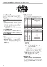
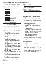
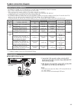
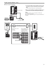
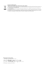
IP connections
12V
IN
LAN
RS-422
PREVIEW
CCU
SIGNAL GND
Personal computer
LAN cable (straight cable)
LAN cable (straight cable)
Max. 100 m
External DC
power supply
AK-HRP200
AK-HCU200
AK-HCU200
Switching hub
(100base-TX)
1.
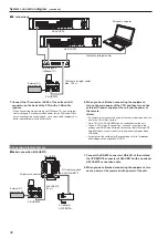
Connect the IP connector <LAN> of the unit and LAN
connector on the back of the CCU with a LAN cable
(option).
• When connecting via a switching hub (100base-TX), use a straight
cable (category 5 or better shielded cable) for the LAN cable. When
not connecting via a switching hub, use a cross cable (category 5 or
better shielded cable) for the LAN cable.
2.
When you have finished connecting the equipment,
turn on the main power of the CCU and then turn on the
external DC power supply of the unit and the power of
the camera.
<Note>
• If a camera is not connected, some of the control functions from the
unit to the CCU will be limited.
• Up to 19 CCUs (AK-HCU200) can be controlled from the unit.
• To use a CCU via an IP connection, you need to configure the
settings with ROP Setup Software (accessory). Before using ROP
Setup Software, connect the unit to the personal computer with a
LAN cable.
• For details on the settings for IP connections, refer to Operations
and Settings on the supplied CD-ROM.
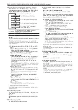
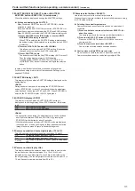
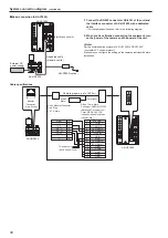
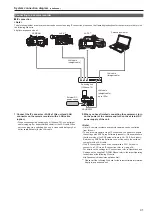
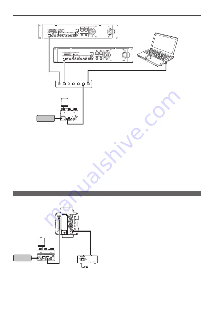
Connecting a remote camera
Serial connection (AW-HE870)
12V
IN
LAN
RS-422
PREVIEW
CCU
SIGNAL GND
AW-CA50T8
(10 m)
External DC
power supply
AK-HRP200
I/F remote connector
AW-HE870
AC adapter
AW-PS510A
DC cable supplied
with AW-HE870
1.
Connect the RS-422 connector <RS-422> of the unit and
the I/F REMOTE connector of AW-HE870 with an optional
AW-CA50T8 connection cable.
2.
When you have finished connecting the equipment, turn
on the power of the camera and the power of the unit.
Summary of Contents for AK-HRP200G
Page 43: ...43 Memo ...


