background image

10

VDTL

HDTL

CRSP

0

0

0

PEAK1

PEAK2

1

2

LDP

DARK

10%

2

CORNER

SRC

+CLP

–CLP

3

G

0

0

KNEE

CRM

CRSP

CRED

0

0

0

0

S

K

I

N


D

T

L S

K

I

N

_

L

V

L

ON

LOW

ZEB

PHAS

WIDTH

CRSP

ON

123

15

2

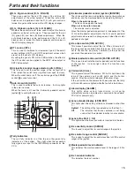
–CLP: Detail edge undershoot clip

This is used to limit the length of the undershoot parts of
the detail edge components.

+KNE: Detail edge overshoot knee

This function applies the knee to the detail edge overshoot
parts.

–KNE: Detail edge undershoot knee

This function applies the knee to the detail edge
undershoot parts.

KDTL: Knee detail

This is used to boost detail components of the parts where
the knee has been applied.

CRSP: Knee detail crisp

This is used to remove the very faint noise components
below the level set from the knee detail components.

FREQ: Knee detail boost frequency

This is used to select the knee detail boost frequency.

+CLP: Knee detail edge overshoot clip

This is used to limit the length of the overshoot parts of the
knee detail edge components.

–CLP: Knee detail edge undershoot clip

This is used to limit the length of the undershoot parts of
the knee detail edge components.

+KNE: Knee detail edge overshoot knee

This function applies the knee to the knee detail edge
overshoot parts.

–KNE: Knee detail edge undershoot knee

This function applies the knee to the knee detail edge
undershoot parts.

SKIN_DTL: Skin tone detail

This is used to set the skin tone detail function to ON or
OFF.

SKIN_LVL: skin tone detail level

This is used to set the chroma saturation of the parts
where the skin tone detail is applied.

FZEB: Skin tone area zebra

This is used to set whether or not to apply zebra to the
areas where coring is applied as the skin tones to the Y
signals in the PM output.

PHAS: Skin tone area phase

This is used to move the areas recognized as the skin
tones in the range of 153 to 93 along the Q axis on the
color vector display.

WIDTH: Skin tone area width

This is used to widen the areas recognized as the skin
tones in the range of 1 to 20 along the I axis on the color
vector display.

CRSP: Skin tone detail crisp

This is used to remove the very faint noise components
below the level set from the skin tone detail components.

=

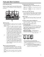
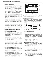
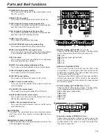
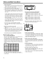
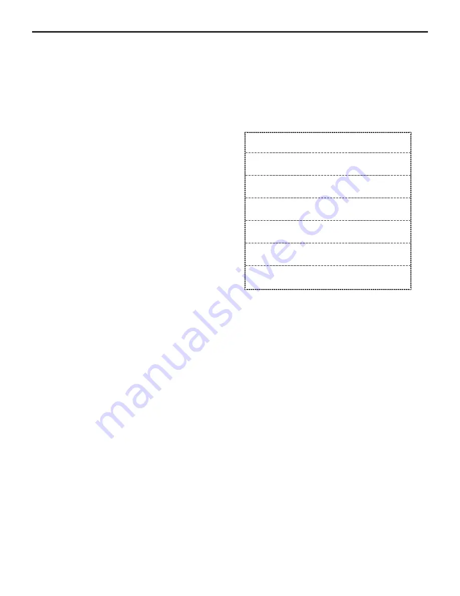
SDTV detail control switches [SD.DTL CONTROL]

This switch is selected to change the amount by which the
picture quality in the detailed parts of the SDTV video
output has been enhanced (by which the relative
hardness/softness has been adjusted).  When it is
selected, its lamp lights.

VDTL: Vertical detail level

This is used to adjust the amount of vertical detail.

HDTL: Horizontal detail level

This is used to adjust the amount of horizontal detail.

CRSP: Crisp

This is used to set the maximum amplitude of the very
faint noise components which are to be removed from the
detail components.

PEAK1: Peak frequency

This is used to select one of the two contour correction
frequency bands.

PEAK2: Peak frequency

This is used to select one of the two contour correction
frequency bands.

LDP: Level depend

This function removes the detail in the dark parts by
means of a coefficient dependent upon the video signal
level so that the dark parts will not appear unnatural.

DARK: Dark detail

This function boosts the detail in the dark parts.

CORNER: Corner detail

This function boosts the detail around the edges of the
screen.

SRC: Detail source

This is used to select the source signals for creating the
detail components.

Parts and their functions

Summary of Contents for AKHRP931 - RMT PANEL - AKHC930

Page 1: ...AK HRP931P Before attempting to connect operate or adjust this product please read these instructions completely Remote Operation Panel ...

Page 2: ...eil numérique de la classe A est conforme à la norme NMB 003 du Canada CAUTION TO REDUCE THE RISK OF FIRE OR SHOCK HAZARD AND ANNOYING INTERFERENCE USE ONLY THE RECOMMENDED ACCESSORIES FCC Note This device complies with Part 15 of the FCC Rules To assure continued compliance follow the attached installation instructions and do not make any unauthorized modifications This equipment has been tested ...

Page 3: ... the designated multi cable is used to connect the ROP and CCU the distance between these two components can be extended to a maximum of 50 meters Contents Overview 3 Accessories 3 Operating precautions 4 Parts and their functions 5 ROP operation panel 5 ROP connector panel 16 Connections 16 System component connections 16 Reference files 16 Calling reference files 16 Storing reference files 16 Ex...

Page 4: ...F or above 104 F may adversely affect the internal parts Turn off the power before connecting or disconnecting the cables Do not use the ROP outdoors Maintenance Disconnect the multi cable and wipe the panels with a dry cloth To remove stubborn dirt soak a cloth in some diluted kitchen detergent and wring it out well and then wipe the panels gently Caution Avoid using benzine paint thinners and ot...

Page 5: ... s operations are cancelled protected status when this switch is pressed while its lamp is lighted while the CCU s power and the camera s power is ON However even when the ROP ON switch lamp is off the panel s GAIN FLARE and DTL controls can be operated provided that the active indicator is lighted It is also possible to operate the iris close switch irrespective of the ROP ON switch setting provi...

Page 6: ...ch CHARACTER This is used to set the characters to be displayed on the PM to ON or OFF 9 OPT FAN CABLE ALARM 1 2 3 1Optical transmission alarm indicator OPT ALARM This is the optical transmission warning indicator Lighted The indicator lights when the optical signals received in the transmission between the camera and CCU are too weak or when a CCU optical transmission receiver unit data error has...

Page 7: ...D DTL OFF MODE This is used to cancel the detail enhancer function that enhances adjusts the relative hardness softness of the picture quality in the detailed parts of the HDTV video output Its lamp lights when the function is canceled SDTV detail OFF switch SD DTL OFF MODE This is used to cancel the detail enhancer function that enhances adjusts the relative hardness softness of the picture quali...

Page 8: ... select the video signals targeted for black and white shading correction from among the R G and B signals The lamp of the selected switch lights 4Knee control switch KNEE CONTROL This is selected to adjust the knee slope and knee point When it is selected its lamp lights The menu is two tiered the adjustment items for the knee point are displayed on the first tier and the adjustment items for the...

Page 9: ... where the white balance was attained in the range of 800 to 800 After the white balance is adjusted 0 is set as the adjustment value VDTL Vertical detail level This is used to adjust the amount of vertical detail HDTL Horizontal detail level This is used to adjust the amount of horizontal detail CRSP Crisp This is used to set the maximum amplitude of the very faint noise components which are remo...

Page 10: ... to set whether or not to apply zebra to the areas where coring is applied as the skin tones to the Y signals in the PM output PHAS Skin tone area phase This is used to move the areas recognized as the skin tones in the range of 153 to 93 along the Q axis on the color vector display WIDTH Skin tone area width This is used to widen the areas recognized as the skin tones in the range of 1 to 20 alon...

Page 11: ...ed to remove the very faint noise components below the level set from the skin tone detail components Matrix control switch MATRIX CONTROL This is pressed to change the correction amounts for the R G R B G R G B B R and B G chroma saturation R G R B G R G B 1 0 0 1 1 0 B R B G 0 0 M T X 1 2 G A I N P H A S E C y _ B 0 0 MTX 12 GAIN PHASE These are used to select the following 12 axis matrix adjust...

Page 12: ...e R B or G shading switch has been selected ANLG CCU analog output setting This is used to set the analog output of the CCU to the HD or SD component O_SEL Output select This is used to set the analog output of the CCU to RGB or YPbPr SYNC Sync waveform addition setting This is used to select whether to add the sync waveform to the analog output TYPE Analog sync phase coarse adjustment This is use...

Page 13: ...ene or the data in the adjustment data that can be transferred to another camera to be saved in or called from eight files that serve as scene files POWER FAN Fan power switch This is used to set the power of the camera head s fan to ON OFF or AUTO SPEED FAN Fan speed This is used to set the speed of the camera head s fan 2D M Component 2 dimensional low pass filter This is used to set whether to ...

Page 14: ...e waveform monitor WFM and picture monitor The output mode can be changed by selecting the MSEL and MLINK settings on the fourth tier of the SYSTEM screen If MLINK is set to ON when BLACK SHADING and WHITE SHADING are to be adjusted the monitor display is also switched temporarily in linkage with the R G and B shading switches D Monitor selector switch R R R R R HDTV Y G P M SDTV Y G P M G G G G G...

Page 15: ...d B pedestal adjustments the R G and B pedestal adjustment values remain unchanged even when the master pedestal is changed M Iris active switch IRIS ACTIVE This makes it possible to adjust the iris When its lamp is off the iris cannot be controlled from this panel If the switch is set to ON and the iris priority is returned to this panel the panel can then exercise iris control N Master pedestal ...

Page 16: ...OP able be certain to set CCU s camera power switch to OFF This function stores data in the files containing the user s basic settings user files and calls the data from them It is also possible to call data from the file in which the initial camera settings were stored at the factory factory file Calling reference files 1Factory file Press scene file switch 4 while holding down CALL The file call...

Page 17: ...ENS X0 8 PED IRIS EXT CALL SENSE RANGE G B R PED Remote Operation Panel AK HRP930P 17 Specifications External dimension drawings CCU control Control signals camera CCU control Power supply DC 12 V Tally control signals RCP control Control signals fader control Power supply DC 12 V PREVIEW control Control signals Maximum cable extension distance 50 meters Operating temperature range 32 F to 104 F 0...

Page 18: ...os Angeles CA 90068 323 436 3500 Government Marketing Department 52 West Gude Drive Rockville MD 20850 301 738 3840 Broadcast PARTS INFORMATION ORDERING 9 00 a m 5 00 p m EST 800 334 4881 24 Hr Fax 800 334 4880 Emergency after hour parts orders 800 334 4881 TECHNICAL SUPPORT Emergency 24 Hour Service 800 222 0741 Panasonic Canada Inc 5770 Ambler Drive Mississauga Ontario L4W 2T3 905 624 5010 Panas...

Reviews: