
14
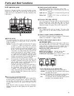
Parts and their functions
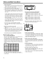
Calling scene file data
1.
From among the 1 to 8 scene file switches, press the
number of the switch that corresponds to the scene file
which is to be called and light its lamp.
2.
The scene file is now read. The data read from the scene
file is input into the current file and then output.
3.
When the scene file is read, the data left in the current file
until that moment is temporarily saved. The lamp of the
scene file switch remains lighted even after the data has
been called.
To stop calling the scene file, press the scene file switch
with the lighted lamp and turn its lamp off. The data that
was temporarily saved before the scene file was called is
now returned to the current file as the setting information,
and the setting statuses established prior to the scene file
call are also restored.
If a scene file switch other than the one with the lighted
lamp is pressed and its lamp is lighted, the scene file
corresponding to the number of the scene file switch with
the now lighted lamp is called.
2
Scene file storage switch [SCENE FILE STORE]
This is pressed to store setting or adjustment data as
scene files.
Saving the current file as a scene file
1.
When the scene file storage switch is pressed, its lamp
lights up.
2.
When the switch with the number of the scene file in which
the data is to be saved is pressed and its lamp is lighted,
the saving of the current file starts and, upon completion,
the lamp of the scene file storage switch goes off.
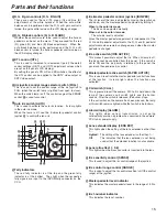
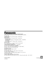
3
Scene file selector switch [SCENE 1-4/5-8 SELECT]
The R, G and B switches can be selected simultaneously.
The RGB outputs on the WFM display are shown as a
parade display.
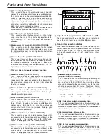
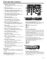
Monitor selector switches
[R, G, B, SEQ, ENC MONITOR]
These are used to select what is to be displayed on the
waveform monitor (WFM) and picture monitor.
The output mode can be changed by selecting the MSEL
and MLINK settings on the fourth tier of the SYSTEM screen.
If MLINK is set to ON when BLACK SHADING and WHITE
SHADING are to be adjusted, the monitor display is also
switched temporarily in linkage with the R, G and B shading
switches.
D
Monitor selector
switch
R
R
R
R
R
HDTV
Y/-G
P-M
SDTV
Y/-G
P-M
G
G
G
G
G
B
B
B
B
B
SEQ
RGB
Y
RGB
Y/-G
ENC
RGB
Y
VBS
VBS
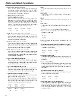
E
GAIN
-6
-3
0
3
6
9
12
2
1
1
Gain selection status display [GAIN display]
This displays the video input sensitivity gain.
–6 dB:
The input sensitivity is increased by –6 dB.
–3 dB:
The input sensitivity is increased by –3 dB.
0 dB:
The input sensitivity is increased by 0 dB (standard
setting).
3 dB:
The input sensitivity is increased by 3 dB.
6 dB:
The input sensitivity is increased by 6 dB.
9 dB:
The input sensitivity is increased by 9 dB.
12 dB:
The input sensitivity is increased by 12 dB.
2
Gain setting increment, decrement switches (
2
,
1
)
These are used to set the gain selection.
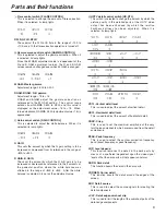
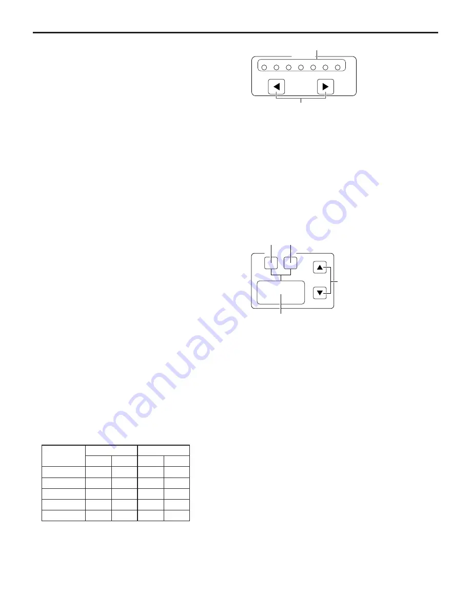
F
SHUTTER
ON
VAR
4
3
2
1
1
Shutter switch [SHTR ON]
This is used to set the electronic shutter mode or V.RES
mode, which has already been set, to ON or OFF. When
it is selected, its lamp lights. The 4-digit LED display
shows the reciprocal of the shutter value (CCD charge
storage time) or the V.RES mode.
2
Shutter mode selector switch [VAR]
This is used to select the step electronic shutter mode or
the continuously variable shutter mode. Its lamp lights up
when the continuously variable shutter mode has been
selected.
3
Shutter/V.RES display
In the electronic shutter mode, this indicates the reciprocal
of the shutter value; in the vertical high resolution mode, it
indicates the resolution steps (11 to 19).
4
Increment, decrement switches [
3
,
4
]
These are used to change the 4-digit LED display data in
the electronic mode or V.RES mode.
If
4
is pressed in the V.RES mode, the data appears
when “100” is shown as the shutter value on the
shutter/V.RES display.


