AQ-C
ORDERING INFORMATION
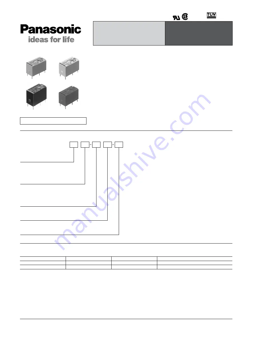
TYPES
1. Input module
Standard packing: Carton: 50 pcs.; Case: 500 pcs.
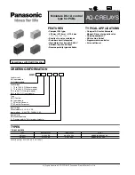
Miniature DIL 1A control
type for PCBs
AQ-C RELAYS
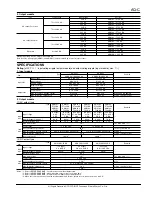
Type
Output voltage
Input voltage
Part No.
AC input
4 to 32 V DC
80 to 250 V AC
AQCD3-IM 100/240 V AC
DC input
4 to 32 V DC
3 to 32 V DC
AQCD3-IM 4/24 V DC
Please contact us about TÜV certified products.
Compliance with RoHS Directive
FEATURES
• Compact DIL type:
L20 mm
×
W10 mm
×
H12.8 mm
(.787
×
.394
×
.504 inch)
• Excellent in noise resistance
• Snubber circuit integrated
• High dielectric strength: 2,500 V
between input and output
• Reverse polarity type available
TYPICAL APPLICATIONS
• Compact AC motor, Solenoid,
Magnet, Driver of magnetic valve
• Copying equipment
• NC machine, Robot
• Programmable controller
• Air conditioners
Load current
Nil:
1A:
AQC
Load voltage
1:
2:
D1:
D3:
Type
Nil:
IM:
T:
ZT:
Input voltage
Output module:
Input module:
5, 12, 24 V DC
4/24 V DC, 100/240 V AC
Input polarity
Nil:
R:
Input module
Output module
75 to 125 V AC (Output module)
75 to 250 V AC (Output module)
3 to 60 V DC (Output module)
4 to 32 V DC (Input module)
DC output
Input module
AC output Random
AC output Zero-cross
Standard polarity
Reverse polarity (Only for output module)
All Rights Reserved © C
OPYRIGHT
Panasonic Electric Works Co., Ltd.


