background image

AQ-C

NOTE

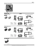
For Cautions for Use.

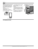
When used for the load less than rated

In the case of the load current less than 
rated, malfunction may result from the 
residual voltage across the both ends of 
the load even if the solid state relay is 
turned off.
Use a dummy resistor as a 
countermeasure.
The total of the current through the 
resistor and the load current must exceed 
the min. rated load current.

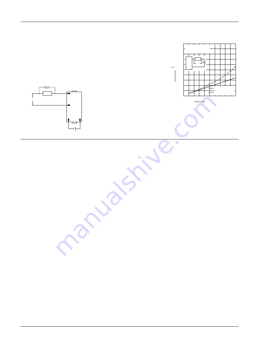
In case the dummy resistor is not used, 
keep in mind that the residual voltage 
becomes as follows:
Example:
For the inductive load by the 5 mA load 
current and the 200 V AC load voltage, 
the load impedance becomes 40 kW and 
Ve/V = 16% is estimated from the below 
graph.
Accordingly, the 32 V voltage remains 
across the both ends of the load when 
the solid state relay is turned off.

• Characteristics of residual voltage 
vs. load impedance

16

1

Load power source

Input power source

5

8

+

Load

R

0

(Dummy resistor)

( + )

( – )

0

20

40

20

40

60

100,%

80

100

60

80

100

Ve

Ve

V

V

SSR

1

2

Load

×

f =  60 Hz
Ve: Residual voltage
V: Power voltage

Power  factor: 1

(resistive  load)
Power  factor: 0.4

(inductive load)

Load impedance, k

All Rights Reserved © C

OPYRIGHT

 Panasonic Electric Works Co., Ltd.

Summary of Contents for AQ-C Relays

Page 1: ...ic strength 2 500 V between input and output Reverse polarity type available TYPICAL APPLICATIONS Compact AC motor Solenoid Magnet Driver of magnetic valve Copying equipment NC machine Robot Programmable controller Air conditioners Load current Nil 1A AQC Load voltage 1 2 D1 D3 Type Nil IM T ZT Input voltage Output module Input module 5 12 24 V DC 4 24 V DC 100 240 V AC Input polarity Nil R Input ...

Page 2: ...1 V DC Output side Load voltage 4 to 32 V DC 4 to 32 V DC Load current 0 1 to 25 mA 0 1 to 25 mA Max OFF state leakage current Max 5µA Max 5µA When 32 V DC applied Max ON state voltage drop Max 1 6 V Max 1 6 V at max carrying current Type Item AQC1A1 ZT5VDC AQC1A1 T5VDC AQC1A1 ZT12VDC AQC1A1 T12VDC AQC1A1 ZT24VDC AQC1A1 T24VDC AQC1A2 ZT5VDC AQC1A2 T5VDC AQC1A2 ZT12VDC AQC1A2 T12VDC AQC1A2 ZT24VDC ...

Page 3: ...itude of 3 mm 1 hour for X Y Z axis Functional 10 to 55Hz double amplitude of 3 mm 10 minutes for X Y Z axis Shock resistance Destructive Min 980 m s2 100 G 5 time each for X Y Z axis Functional Min 980 m s2 100 G 4 time each for X Y Z axis Ambient temperature 30 C to 80 C 22 F to 176 F Storage temperature 30 C to 100 C 22 F to 212 F Operational method Random Turn ON Zero cross Turn OFF Zero cross...

Page 4: ...Tolerance 0 1 004 Schematic 7 62 7 62 10 16 4 1 1 dia 4 043 dia Terminal 1 Terminal 5 Terminal 8 Terminal 16 300 300 400 16 1 Input power source Specified polarities for DC types are shown in the parentheses Load power source 5 8 Load CAD Data 2 Output module AC DC General tolerance 0 5 020 10 2 7 106 0 3 0 3 0 3 0 3 0 3 0 8 0 8 12 5 3 9 2 7 5 5 0 4 0 4 20 10 16 7 62 7 62 AC output Case color Blac...

Page 5: ...ge becomes as follows Example For the inductive load by the 5 mA load current and the 200 V AC load voltage the load impedance becomes 40 kW and Ve V 16 is estimated from the below graph Accordingly the 32 V voltage remains across the both ends of the load when the solid state relay is turned off Characteristics of residual voltage vs load impedance 16 1 Load power source Input power source 5 8 Lo...

Reviews: