Panasonic Corporation Electromechanical Control Business Division
industrial.panasonic.com/ac/e/
Cautions for Use of Solid State Relays
Panasonic Corporation 2022
Soldering
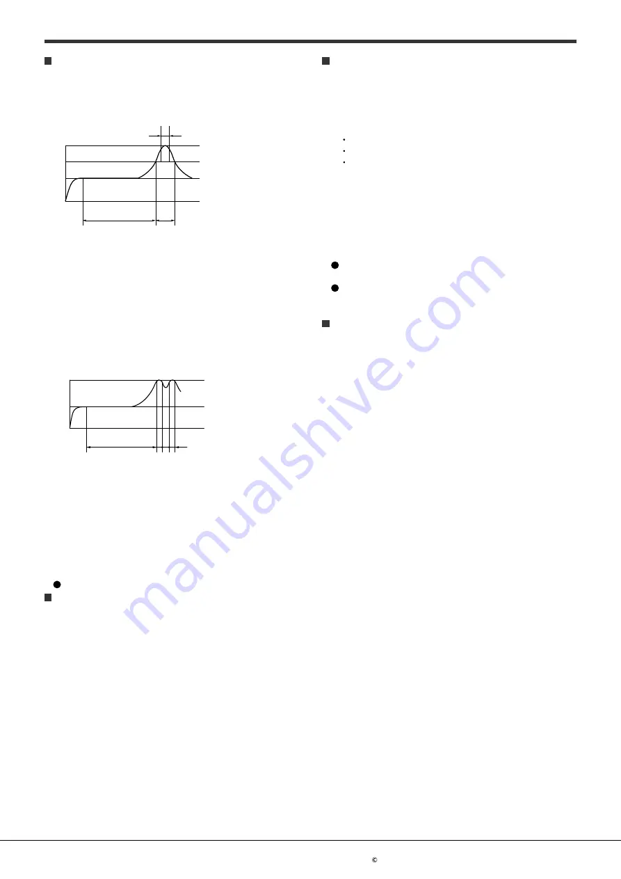
1) When soldering surface-mount terminals, the following
conditions are recommended.
(1) IR (Infrared reflow) soldering method
(Recommended condition reflow: Max. 2 times, measurement
point: soldering lead)
t
3
T
3
T
2
T
1
t
2
t
1
T1 = 150 to 180°C
T2 = 230°C
T3 = 240 to 250°C
t1 = 60 to 120 s
t2 = Within 30 s
t3 = Within 10 s
(2) Other soldering methods
Other soldering methods (VPS, hot-air, hot plate, laser heating,
pulse heater, etc.) affect the relay characteristics differently,
please evaluate the device under the actual usage.
(3) Soldering iron method
Tip temperature: 350 to 400
°C
Wattage : 30 to 60 W
Soldering time : within 3 s
2) When soldering standard PC board terminals, the following
conditions are recommended.
(1) DWS soldering method
(Recommended condition number of times: Max. 1 time,
measurement point: soldering lead *1)
t
3
t
2
t
1
T
1
T
2
T
1
= 120°C
T
2
= Max. 260°C
t
1
= within 60 s
t
2
+t
3
= within 5 s
*1 Solder temperature: Max. 260 °C
(2) Other dip soldering method (recommended condition: 1 time)
Preheating: Max. 120
°C
, within 120 s,
measurement point:
soldering lead Soldering: Max. 260
°C
, within 5 s*,
measurement area: soldering temperature
*Phototriac coupler and AQ-H: within 10 s
(3) Manual soldering method
Tip temperature: 350 to 400
°C
Wattage: 30 to 60 W
Soldering time: within 3 s
We recommend one with an alloy composition of Sn3.0Ag0.5Cu.
Others
1) If an SSR is used in close proximity to another SSR or
heat-generating device, its ambient temperature may exceed
the allowable level. Carefully plan SSR layout and ventilation.
2) Terminal connections should be made by referring to the
associated wiring diagram.
3) For higher reliability, check device quality under actual
operating conditions.
4) To prevent the danger of electrocution, turn off the power
supply when performing maintenance. Although AQ-A (DC
output type) is constructed with insulation for the input/
output terminals and the rear aluminum plate, the insulation
between the input/output and the rear aluminum plate is not
UL approved.
Transportation and storage
1) Extreme vibration during transport may deform the lead or
damage the device characteristics. Please handle the outer
and inner boxes with care.
2) Inadequate storage condition may degrade soldering,
appearance, and characteristics. The following storage
conditions are recommended:
Temperature: 0 to 45 °C
Humidity: Max. 70%RH
Atmosphere: No harmful gasses such as sulfurous acid gas,
minimal dust.
3) Storage of Phototriac coupler (SOP type)
In case the heat stress of soldering is applied to the device
which
absorbs moisture inside of its package, the evaporation of the
moisture increases the pressure inside the package and it may
cause the package blister or crack. This device is sensitive to
moisture and it is packed in the sealed moisture-proof package.
Please make sure the following condition after unsealing.
Please use the device immediately after unsealing.
(Within 30 days at 0 to 45 °C and Max. 70%RH)
If the device will be kept for a long time after unsealing, please
store in the another moisture-proof package containing silica gel.
(Please use within 90 days.)
Water condensation
Water condensation occurs when the ambient temperature changes
suddenly from a high temperature to low temperature at high
humidity, or the device is suddenly transferred from a low ambient
temperature to a high temperature and humidity. Condensation
causes the failures such as insulation deterioration. Panasonic
Corporation does not guarantee the failures caused by water
condensation.
The heat conduction by the equipment the SSR is mounted may
accelerate the water condensation. Please confirm that there is no
condensation in the worst condition of the actual usage. (Special
attention should be paid when high temperature heating parts are
close to the SSR.)
ASCTB400E 202201
ー 7 ー


