Panasonic Corporation Electromechanical Control Business Division
industrial.panasonic.com/ac/e/
PhotoMOS
®
Cautions for Use
Panasonic Corporation 2022
ASCTB65E 202201
About the exposed terminals on the sides of the
package (for VSSOP)
For VSSOP type, as shown in the following figure, part of the input
and output frames are exposed on the sides of the package. Due to
this, please be keep in mind the cautions listed below.
1) Take care to avoid short circuits between exposed terminals,
which may cause insulation deterioration between input and
output, leading to destruction of internal elements.
2) Since the exposed terminals are connected electrically to the
internal element, please refer to the item “
■
Deterioration and
destruction caused by discharge of static electricity”, and
implement sufficient measures to control static electricity.
3) When installing the devices in the vicinity, please keep in mind
that if the exposed frames of adjacent devices get too close, a
short between devices may occur.
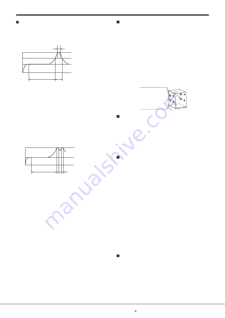
Part of frame on output side
Part of frame on input side
Adjacent mounting
When several PhotoMOS
®
are mounted closely each other or
heat-generating components are mounted close to the PhotoMOS
®
,
the abnormal heating may occur. This abnormal heat may be
caused by the internal element when energized or thermal
interference between the devices. The degree of temperature rise
depends on the mounting layout of the devices and usage condition,
therefore please be sure to use PhotoMOS
®
with reduced load
current after testing under the worst condition of the actual usage.
Transportation and storage
1) Extreme vibration during transport may deform the lead or
damage the PhotoMOS
®
characteristics. Please handle the outer
and inner boxes with care.
2) Inadequate storage condition may degrade soldering,
appearance, and characteristics. The following storage conditions
are recommended:
• Temperature: 0 to 45°C
• Humidity: Max. 70%RH
• Atmosphere: No harmful gasses such as sulfurous acid gas,
minimal dust.
3) Storage before TSON, VSSOP, SON, SSOP, or SOP processing
In case the heat stress of soldering is applied to the PhotoMOS
®
which absorbs moisture inside of its package, the evaporation of
the moisture increases the pressure inside the package and it
may cause the package blister or crack. This device is sensitive
to moisture and it is packed in the sealed moisture-proof package.
Please make sure the following condition after unsealing.
* Please use the device immediately after unsealing.
(Within 30 days at 0 to 30°C and Max. 70%RH)
* If the device will be kept for a long time after unsealing, please
store in the another moisture-proof package containing silica gel.
(Please use within 90 days.)
Water condensation
Water condensation occurs when the ambient temperature changes
suddenly from a high temperature to low temperature at high
humidity, or the device is suddenly transferred from a low ambient
temperature to a high temperature and humidity. Condensation
causes the failures such as insulation deterioration. Panasonic
Corporation does not guarantee the failures caused by water
condensation. The heat conduction by the equipment the
PhotoMOS
®
is mounted may accelerate the water condensation.
Please confirm that there is no condensation in the worst condition
of the actual usage. (Special attention should be paid when high
temperature heating parts are close to the PhotoMOS
®
.)
Soldering
1) Example of surface-mount terminal recommended conditions
(1) IR (Infrared reflow) soldering method
In case of automatic soldering, following conditions should be
observed. (recommended condition reflow: Max. 2 times,
measurement point: soldering lead)
t
3
T
3
T
2
T
1
t
2
t
1
T1 = 150 to 180°C
T2 = 230°C
T3 = 240 to 250°C*
t1 = 60 to 120 s
t2 = Within 30 s
t3 = Within 10 s
*240 to 245°C for SON, VSSOP
and TSON package
(2) Other soldering methods
Other soldering methods (VPS, hot-air, hot plate, laser
heating, pulse heater, etc.) affect the PhotoMOS
®
characteristics differently, please evaluate the device under
the actual usage.
(3) Manual soldering method
Temperature: 350 to 400°C, within 3s, electrical power 30 to
60W
2) Example of through hole terminal recommended conditions
(1) DWS soldering method
In case of automatic soldering, following conditions should be
observed. (recommended condition number of times: Max. 1
time, measurement point: soldering lead *1)
t
3
t
2
t
1
T
1
T
2
T
1
= 120°C
T
2
= Max. 260°C
t
1
= within 60 s
t
2
+t
3
= within 5 s
*1 Solder temperature: Max. 260°C
(2) Other soldering method (recommended condition: 1 time)
Preheating: Max. 120°C, within 120s, measurement point:
soldering lead
Soldering: Max. 260°C, within 10s, measurement area:
soldering temperature
(3) Manual soldering method
Temperature: 350 to 400°C, within 3s, electrical power 30 to
60W
ー 11 ー


