


Panasonic Corporation Electromechanical Control Business Division
industrial.panasonic.com/ac/e/
Panasonic Corporation 2022
ASCTB65E 202201
PhotoMOS
®
Cautions for Use
SAFETY WARNINGS
Do not use the product under conditions that exceed the range
of its specifications. It may cause overheating, smoke, or fire.
Do not touch the recharging unit while the power is on. There
is a danger of electrical shock. Be sure to turn off the power
when performing mounting, maintenance, or repair operations
on the device (including connecting parts such as the terminal
board and socket).
Check the wiring diagrams in the catalog and be sure to
connect the terminals correctly. If the device is energized
with short circuit or any wrong connection, it may cause
unexpected malfunction, abnormal heat or fire.
Derating design
Derating is a significant factor for reliable design and product life.
Even if the conditions of use (temperature, current, voltage, etc.) of
the product are within the absolute maximum ratings, reliability may
be lowered remarkably when continuously used in high load
conditions (high temperature, high humidity, high current, high
voltage, etc.) Therefore, please derate sufficiently below the
absolute maximum ratings and evaluate the device in the actual
condition.
Moreover, regardless of the application, if malfunctioning can be
expected to pose high risk to human life or to property, or if products
are used in equipment otherwise requiring high operational safety, in
addition to designing double circuits, that is, incorporating features
such as a protection circuit or a redundant circuit, safety testing
should also be carried out.
Applying stress that exceeds the absolute maximum
rating
If the voltage or current value for any of the terminals exceeds the
absolute maximum rating, internal elements will deteriorate because
of the overvoltage or overcurrent. In extreme cases, wiring may
melt, or silicon P/N junctions may be destroyed.
Therefore, the circuit should be designed in such a way that the load
never exceed the absolute maximum ratings, even momentarily.
Input voltage (for Voltage-sensitive type)
For rising and dropping ratio of input voltage(dv/dt), maintain Min.
100mV/ms.
Oscillation circuit and control circuit (for CC Type)
The oscillation circuit and control circuit of product may be destroyed
by external noise, surge, static electricity and so on.
For noise effect to peripheral circuits when oscillation circuit
operates, please implement safety measures on the system before
use by verifying operation under the actual design.
Deterioration and destruction caused by discharge of
static electricity
This phenomenon is generally called static electricity destruction,
and occurs when static electricity generated by various factors is
discharged while the PhotoMOS
®
terminals are in contact, producing
internal destruction of the element.
To prevent problems from static electricity, the following precautions
and measures should be taken when using your device.
1) Employees handling PhotoMOS
®
should wear anti-static clothing
and should be grounded through protective resistance of 500kΩ
to 1MΩ.
2) A conductive metal sheet should be placed over the worktable.
Measuring instruments and jigs should be grounded.
3) When using soldering irons, either use irons with low leakage
current, or ground the tip of the soldering iron. (Use of low-voltage
soldering irons is also recommended.)
4) Devices and equipment used in assembly should also be
grounded.
5) When packing printed circuit boards and equipment, avoid using
high-polymer materials such as foam styrene, plastic, and other
materials which carry an electrostatic charge.
6) When storing or transporting PhotoMOS
®
, the environment should
not be conducive to generating static electricity (for instance, the
humidity should be between 45% and 60%), and PhotoMOS
®
should be protected using conductive packing materials.
Unused terminals
The No. 3 terminal is used with the circuit inside the device.
Therefore, do not connect it to the external circuitry with either
connection method A, B or C. (1 Form A 6-pin type)
Short across terminals
Do not short circuit between terminals when device is energized,
since there is possibility of breaking of the internal IC.
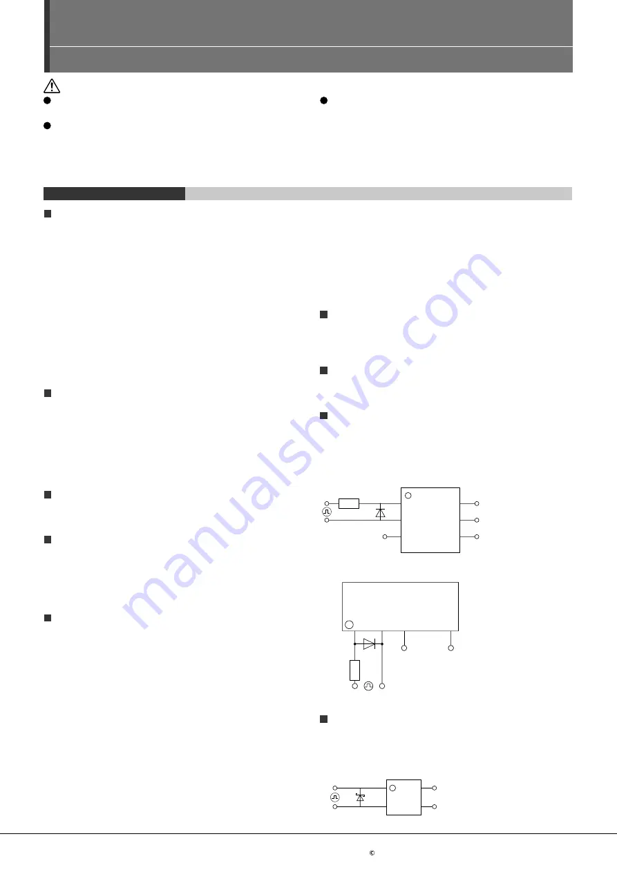
Surge voltages at the input
If reverse surge voltages are present at the input terminals, connect
a diode in reverse parallel across the input terminals and keep the
reverse voltages below the reverse breakdown voltage.
Typical circuits are below shown.
1) 6-pin
1
2
3
6
5
4
2) Power type
3
2
1
4
Reverse voltages at the input (for CC Type)
If reverse voltages are present at the input terminals, for example,
connect a schottky barrier diode in reverse parallel across the input
terminals and keep the reverse voltages below the reverse
breakdown voltage. Typical circuit is shown below.
1
2
4
3
PhotoMOS
®
Cautions for Use
ー 8 ー


