background image

AV3,AVM3/AVT3,AVL3

NEW SUBMINIATURE 

SWITCHES 

WITH HIGH PRECISION

AV (FS•FS-T) 

SWITCHES

VDE

FS

FS-T

Compliance with RoHS Directive

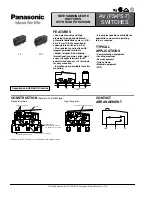
FEATURES

• Consistent quality and high 
precision through sophisticated 
automatic fabrication system —O.P.: 
8.4

±

0.3 mm (O.P.of conventional 

subminiature switches: 8.4

±

0.5)

• Flux-resistant construction with 
integrally molded terminals
• Solder terminal; Self-standing, 
internationally common pitch, right 
angle, left angle terminals for PC 
board; Quick connect .110 terminals 
for easy mounting
• Insulation guard available for safety 
mounting

• 2 lever pivot positions available for 
applications where low operating 
force is required

TYPICAL 
APPLICATIONS

• Communication equipment
• Vending machines
• Security systems
• Data systems
• Medical equipment
• VCR

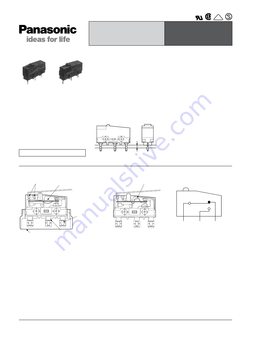
PC board thickness: 
1.6 mm

CONSTRUCTION 

(Example: AV3/AVM3 type)

Standard version

Long life version

Remark: As for FS-T switches, the terminals are the different shape.

2 lever pivot positions

Spring

Optional insulation guard

Flux resistant construction

Solder-terminal
Self-standing PC terminal
.110 Quick connect terminal

Arch-shaped independent spring

CONTACT 
ARRANGEMENT

COM

NC

NO

All Rights Reserved © C

OPYRIGHT

 Panasonic Electric Works Co., Ltd.

Summary of Contents for AV(FS-FS-T)

Page 1: ...ounting Insulation guard available for safety mounting 2 lever pivot positions available for applications where low operating force is required TYPICAL APPLICATIONS Communication equipment Vending machines Security systems Data systems Medical equipment VCR PC board thickness 1 6 mm CONSTRUCTION Example AV3 AVM3 type Standard version Long life version Remark As for FS T switches the terminals are ...

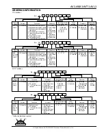
Page 2: ... Short hinge lever 2 Hinge lever 3 Long hinge lever 4 Simulated roller lever 5 Roller lever Nil Standard 11 forward 5 1 47 N Operating force by pin plunger max Lever position International standard Nil AgNi alloy 61 Gold clad triple layer 3 UL CSA VDE SEMKO Ex AV M3 2 0 2 3 Type of switch Terminals Actuators Contacts 2 Solder terminal 4 PC terminal 8 110 Quick connect terminal AVT3 FS T switch Ver...

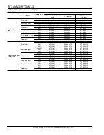
Page 3: ...13 AV3500613 0 49N AV3202613 AV3102613 AV3302613 AV3402613 AV3502613 0 98N AV3204613 AV3104613 AV3304613 AV3404613 AV3504613 Short hinge lever 0 098N AV3210613 AV3110613 AV3310613 AV3410613 AV3510613 0 20N AV3212613 AV3112613 AV3312613 AV3412613 AV3512613 0 39N AV3214613 AV3114613 AV3314613 AV3414613 AV3514613 Hinge lever 0 078N AV3220613 AV3120613 AV3320613 AV3420613 AV3520613 0 16N AV3222613 AV3...

Page 4: ...ever 0 20N AV36523 AV37523 AV38523 0 39N AV36543 AV37543 AV38543 Gold clad triple layer contact type Pin plunger 0 25N AV3600613 AV3700613 AV3800613 0 49N AV3602613 AV3702613 AV3802613 0 98N AV3604613 AV3704613 AV3804613 Short hinge lever 0 098N AV3610613 AV3710613 AV3810613 0 20N AV3612613 AV3712613 AV3812613 0 39N AV3614613 AV3714613 AV3814613 Hinge lever 0 078N AV3620613 AV3720613 AV3820613 0 1...

Page 5: ...VT32523 AVT34523 AVT38523 0 39N AVT32543 AVT34543 AVT38543 Gold clad triple layer contact type Pin plunger 0 25N AVT3200613 AVT3400613 AVT3800613 0 49N AVT3202613 AVT3402613 AVT3802613 0 98N AVT3204613 AVT3404613 AVT3804613 Short hinge lever 0 098N AVT3210613 AVT3410613 AVT3810613 0 20N AVT3212613 AVT3412613 AVT3812613 0 39N AVT3214613 AVT3414613 AVT3814613 Hinge lever 0 078N AVT3220613 AVT3420613...

Page 6: ...erminal Left angle terminal 110 Quick connect Without guard With guard With opposite side guard AgNi alloy contact type Pin plunger 1 47N AVM36053 AVM37053 AVM38053 Short hinge lever 0 59N AVM36153 AVM37153 AVM38153 Hinge lever 0 54N AVM36253 AVM37253 AVM38253 Long hinge lever 0 44N AVM36353 AVM37353 AVM38353 Simulated roller lever 0 54N AVM36453 AVM37453 AVM38453 Roller lever 0 59N AVM36553 AVM37...

Page 7: ...tal parts Between each terminal and ground 1 000 Vrms 1 500 Vrms 1 500 Vrms Vibration resistance Pin plunger type 10 to 55 Hz at single amplitude of 1 5mm Contact opening max 1 msec Shock resistance Pin plunger type Contact opening less than 1 msec 294 m s2 min O F 0 98 N 147 m s2 min O F 0 49 N 294 m s2 min O F 0 98 N 147 m s2 min O F 0 49 N 49 m s2 min O F 0 25 N 294 m s2 min Contact resistance ...

Page 8: ...N 0 029N 4th digit number of Part No O F max R F min P T max M D max O T max O P 0 2 8mm 0 8mm 1 2mm Distance from mounting holes 11 65 0 8mm Distance from stand off FS 15 05 0 9mm FS T 14 95 0 9mm 2 0 16N 0 015N 4 0 34N 0 029N 5 0 54N 0 034N 4th digit number of Part No O F max R F min P T max M D max O T max O P 0 2 5mm 0 5mm 0 8mm Distance from mounting holes 14 5 0 8mm Distance from stand off F...

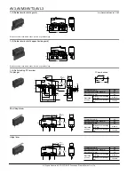
Page 9: ...Pretravel Max mm 0 6 Movement differential Max mm 0 1 Overtravel Min mm 0 4 Operating position Distance from mounting hole mm 8 4 0 3 Distance from standoff mm 11 8 0 4 3 1 2 0 05 dia 8 7 0 1 15 4 0 1 Short hinge lever 12 85 5 0 NC NO C 0 4 2 5 max 6 6 4 0 12 2 O P P T 0 9 8 8 O P 0 8 Pretravel Max mm 2 5 Movement differential Max mm 0 5 Overtravel Min mm 0 8 Operating position Distance from mount...

Page 10: ...tance from standoff mm 15 05 0 9 Roller lever 3 2 5 0 dia NC NO C 5 15 0 4 2 5 max 17 9 O P P T 0 9 14 5 O P 0 8 Pretravel Max mm 2 5 Movement differential Max mm 0 5 Overtravel Min mm 0 8 Operating position Distance from mounting hole mm 14 5 0 8 Distance from standoff mm 17 9 0 9 1 5 Internationally common pitch PC terminal P T 0 6max 4 0 2 4 1 3 4 0 3 2 7 4 6 C0 3 7 62 0 1 19 8 0 3 7 62 0 1 O P...

Page 11: ... board terminal Pin plunger 6 4 3 2 7 0 1 2 0 5 16 1 8 8 19 8 NO NC C 0 3 0 2 0 1 0 6 max 2 4 9 5 7 6 4 0 8 4 P T 6 7 7 7 3 3 0 05 0 1 2 4 2 5 0 3 0 1 0 1 O P 0 3 2 4 dia 0 1 0 05 PC board pattern 10 9 Button position 8 8 0 1 16 1 0 1 3 1 35 to 1 50 dia Pretravel Max mm 0 6 Movement differential Max mm 0 1 Overtravel Min mm 0 4 Operating position Distance from mounting hole mm 8 4 0 3 Distance fro...

Page 12: ...8 12 85 Pretravel Max mm 2 8 Movement differential Max mm 0 8 Overtravel Min mm 1 2 Operating position Distance from mounting hole mm 11 65 0 8 Distance from standoff mm 14 95 0 9 Roller lever NO NC C 3 2 5 0 dia 5 15 0 4 2 5 max P T 14 5 O P 0 8 Pretravel Max mm 2 5 Movement differential Max mm 0 5 Overtravel Min mm 0 8 Operating position Distance from mounting hole mm 14 5 0 8 Distance from stan...

Page 13: ...min 1 minute after soldering Also no tensile strength of lead wires should be applied to terminals 3 Regarding connector connections 110 quick connect terminals For making connections a dedicated receptacle for 110 quick connect terminals should be used and the terminals should be inserted parallel to the receptacle Consideration should be given to mounting so that no tensile load is applied to th...

Reviews: