background image

13

Installation and connections

(Be sure to ask your dealer.)

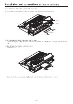
Turn off the power of the unit, and disconnect the power cable.

Loosen the two screws of SLOT A or SLOT B at the back of the unit, and remove the blank panel.

Screw

Blank panel

Screw

SLOT A

SLOT B

Align the option board with the guide rails, and insert it slowly. 
Insert it until it will go no further. Take care not to exert excessive force while doing this since that may damage the connector 
inside.

Mount the option board in place using the two screws. 

Clamping torque:

 0.7 N•m

Y

Pb

Pr

DVI-I

DVI / ANALO

G  OUTPUTS

Screw

Screw

After connecting the necessary cables, plug the power cable into the power outlet, and turn on the power.

Summary of Contents for AV-HS410

Page 1: ...ng this unit be sure to take the time to read through Basics to ensure that the unit will be installed correctly This manual Basics is also contained as a PDF file on the CD ROM supplied with the unit Operations and Settings The Operations and Settings describes how to operate the unit and how to establish its settings The Operations and Settings is contained as a PDF file on the CD ROM supplied w...

Page 2: ... p p Intel and Intel CoreTM are trademarks or registered trademarks of Intel Corporation in the United States and other countries p p Adobe and Reader are either registered trademarks or trademarks of Adobe Systems Incorporated in the United States and or other countries p p SDHC Logo is a trademark of SD 3C LLC p p Primatte is a registered trademark of IMAGICA DIGIX Inc p p The copyrights of Prim...

Page 3: ...erence use the recommended accessories only CAUTION In order to maintain adequate ventilation do not install or place this unit in a bookcase built in cabinet or any other confined space To prevent risk of electric shock or fire hazard due to overheating ensure that curtains and any other materials do not obstruct the ventilation CAUTION The mains plug of the power supply cord shall remain readily...

Page 4: ... FCC NOTICE USA This class A digital apparatus complies with Canadian ICES 003 IMPORTANT SAFETY INSTRUCTIONS 1 Read these instructions 2 Keep these instructions 3 Heed all warnings 4 Follow all instructions 5 Do not use this apparatus near water 6 Clean only with dry cloth 7 Do not block any ventilation openings Install in accordance with the manufacturer s instructions 8 Do not install near any h...

Page 5: ... and their functions 17 1 1 Control panel 17 1 1 1 Crosspoint area 18 1 1 2 Memory wipe pattern number key area 20 1 1 3 User button area 21 1 1 4 Transition area 21 1 1 5 Display area 23 1 1 6 Positioner area 25 1 1 7 Memory card area 26 1 2 Rear panel area 27 2 Preparations 28 2 1 Turning the unit s power on and off 28 2 2 Basic menu operations 29 2 2 1 Menu configuration and operations 29 2 2 2...

Page 6: ...CONVENIENCE OR LOSS OR DAMAGE ARISING OUT OF THE SYSTEM COMBINED BY THE DEVICES OF THIRD PARTY 6 ANY INCONVENIENCE DAMAGES OR LOSSES RESULTING FROM ACCIDENTS CAUSED BY AN INADEQUATE INSTALLATION METHOD OR ANY FACTORS OTHER THAN A DEFECT IN THE PRODUCT ITSELF 7 LOSS OF REGISTERED DATA CAUSED BY ANY FAILURE 8 ANY DAMAGE OR CLAIMS DUE TO LOSS OR LEAKAGE OF IMAGE DATA OR SETTING DATA SAVED ON THIS UNI...

Page 7: ...SD materials can be embedded in HD images with no deterioration in the image quality p p The video process function is incorporated in all the SDI input connectors SDI IN 1 to SDI IN 8 to make it possible to adjust the colors at the input stage of the switcher Sophisticated multi view display function p p One channel is provided for the multi view display function The user can select whether the s...

Page 8: ...n the home page whose address is provided below http pro av panasonic net For the installation procedure follow the steps in the directions which are contained in the download file This unit comes with a built in 178 0 mm 7 inch color display 178 0 mm effective picture area measured diagonally p p The setting menus are viewed on this display p p The display shows images PGM PVW MV of the input sig...

Page 9: ...2 lines AV HS04M4 Analog Output Board Analog component output 2 lines AV HS04M5 DVI Analog Output Board DVI I output 1 line Analog component output 1 line AV HS04M6 Analog Composite Input Board Analog composite input 2 lines AV HS04M7 SDI Output Board SDI output 2 lines AV HS04M8 Full HD DVI Input Board DVI D input 2 lines Supported Required computer environment Use a host computer that satisfies ...

Page 10: ...nds of images produced may have an adverse effect on the viewer s physical well being Built in display LCD monitor Leaving the built in display on with the same image over a long period of time may result in temporary afterimage burn in Such afterimages are usually resolved when ordinary moving images are displayed for a while The liquid crystal parts are highly precise with 99 99 of the pixels ef...

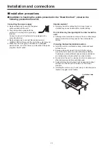
Page 11: ...to strong impact or vibration may cause trouble and or malfunctioning Do not allow any foreign objects to enter inside the unit p p Allowing water metal items scraps of food or other foreign objects inside the unit may cause a fire and or electric shocks Choosing the best installation location p p Install the unit on a sufficiently strong stable and level surface for use p p Ensure a space of at l...

Page 12: ...o 1 Y C separation mode INPUT5 7 1 Y C separation mode IN A1 IN B1 2 2 3 Y C separation mode INPUT6 8 3 Y C separation mode IN A2 IN B2 4 4 5 NTSC SETUP 5 NTSC SETUP 6 Reserved 6 Reserved 7 7 8 8 When an option board AV HS04M1 AV HS04M2 or AV HS04M6 has been installed in the unit the settings established by the selection positions for the following switches are not reflected Select the settings us...

Page 13: ...A SLOT B 3 Align the option board with the guide rails and insert it slowly Insert it until it will go no further Take care not to exert excessive force while doing this since that may damage the connector inside 4 Mount the option board in place using the two screws Clamping torque 0 7 N m Y Pb Pr DV I I DV I AN AL OG OU TP UT S Screw Screw 5 After connecting the necessary cables plug the power c...

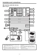
Page 14: ...D 2 TALLY GPI 2 Dsub 15 Editing controller Aux panel VTR etc Switching hub COM Dsub 9 EDITOR Dsub 9 LAN RJ45 Remote camera Aux panel Computer 4 5 DVI D IN Scaler DVI D Input 1 When external synchronization is selected as the reference signal setting the reference signal is input When internal synchronization is selected the reference signal is output 2 When external synchronization is selected as ...

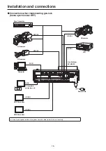
Page 15: ...DVI D OUT SV NM 4 3 SDI OUTPUTS 1 2 5 8 7 6 5 4 3 2 1 SDI INPUTS EDITOR COM TALLY GPI 2 TALLY GPI 1 REF BOOT Power cable DVI D DVI D HD SDI HD SDI Live Switcher AV HS410 HD SDI HD camera Computer PC monitors projectors etc HD SDI monitor HD SDI monitor HD SDI HD camera HD camera VTR HD SDI HD SDI Sync Generator Use a 3 point power outlet as the power source in order to earth the unit securely ...

Page 16: ...LOT A IN OUT A1 IN OUT A2 IN OUT B1 IN OUT B2 SLOT B DVI D IN DVI D OUT SV NM 4 3 SDI OUTPUTS 1 2 5 8 7 6 5 4 3 2 1 SDI INPUTS EDITOR COM TALLY GPI 2 TALLY GPI 1 REF BOOT Pr Pb Y Pr Pb Y ANALOG INPUTS Power cable DVI D DVI D HD SDI HD SDI Live Switcher AV HS410 DVD player Computer PC monitors projectors etc HD SDI monitor HD SDI monitor HD Component HD camera HD camera HD camera VTR HD Component H...

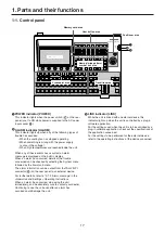
Page 17: ...e power is supplied to the AC power input socket 2ALARM indicator ALARM This indicator lights up when any of the following types of trouble has occurred When the cooling fan has stopped operating When something is wrong with the power supply a drop in the voltage When high temperatures are reached inside the unit When any of these events has occurred an alarm message is displayed on the built in d...

Page 18: ...d as the Bus Mode item by selecting the Config menu following by the Operate sub menu Refer to 1 1 3 Selecting the bus mode Operations and Settings Operating Instructions 6 AUX bus selector buttons AUX BUS DELEGATION Select the bus to be operated using the AUX bus crosspoint buttons 7 The selected button lights KEY This button is used to change the AUX bus crosspoint buttons into the source select...

Page 19: ...X DISP buses AUX DISP SOURCE These buttons are used to select the AUX bus sources while the AUX1 to AUX4 buttons among the AUX bus selector buttons 6 are lit These buttons are used to select the DISP bus sources while the DISP button among the AUX bus selector buttons 6 is lit The buttons light up in amber when they are pressed MV This is used to select the multi view display signals for the AUX b...

Page 20: ...ection menu is displayed on the built in display When the F1 is rotated the pattern page is changed Refer to 1 2 Wipe Operations and Settings Operating Instructions Memory operation buttons SHOT MEM EVENT MEM These buttons are used to select the memory type The number keys 1 to 10 are used to carry out operations and register and call settings PLUGIN MEM1 PLUGIN MEM2 Press these buttons to use plu...

Page 21: ...n when the AUTO button or fader lever has been operated When the KEY button is pressed and it is selected its indicator lights in amber If the BKGD button is now pressed the indicator goes off and the de selected status is established When the BKGD button and KEY button are pressed at the same time both buttons are set to the selected status MIX WIPE selection status LEDs These light up to indicat...

Page 22: ...P button PinP1 ON PinP2 ON This button is used to execute fade in or fade out of the picture in picture for the transition time which has been set on the Time menu DSK ON button This button is used to execute fade in or fade out of downstream key for the transition time which has been set on the Time menu Wipe direction selection buttons WIPE DIRECTION N R R These buttons are used to select the di...

Page 23: ...ges waveforms and menus are displayed by operating the display mode buttons and menu selection buttons To show images on the built in display press the DISP button of the AUX bus selector buttons 6 and light its indicator MV PVW and PGM images can be displayed Display mode buttons DISPLAY These buttons are used to select what is to be displayed on the built in display MENU MODE Each time this butt...

Page 24: ...ectorscope display Menu selection buttons MENU SELECT Each time one of these buttons is pressed the menu of the function indicated at the top or bottom of the button is selected The button of a selected menu lights up in amber MENU HOLD button This button is used to keep a menu on the display When it is pressed while a menu is displayed the menu displayed will not be switched to another menu even ...

Page 25: ...he settings take effect only when the following menu items have been selected Positioner Rotary encoder Valid menu X Y Z Switch PinP1 PinP2 Position adjustments Size adjustments size increased by rotating the encoder clockwise and reduced by rotating it counterclockwise Hold switch down to restore initial values X Y Z All PinP1 and PinP2 menus WIPE BKGD Start position adjustments Hold switch down ...

Page 26: ...mory card q qConcerning memory cards Memory cards used with the unit should conform to SD or SDHC standards Be sure to format cards using the unit Memory cards with the following capacity can be used for the unit SDXC memory cards are not available for this product SD from 8 MB to 2 GB SDHC from 4 GB to 32 GB For the latest information not available in the Operating Instructions visit the followin...

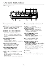
Page 27: ...n be allocated by the menus p p The DVI I connector cable cannot be used Reference input connector BB output connector REF Loop through output in the external sync mode If the loop through output is not going to be used provide a 75 ohm termination BB signals output from both connectors in the internal sync mode LAN connector LAN RJ 45 10 100 Base TX Refer to 4 External interfaces Operations and S...

Page 28: ...nds the crosspoint buttons light up 2 Several seconds after the crosspoint buttons have lit up the opening screen appears on the built in display At this point it becomes possible to select the crosspoints 3 Menu operations can be performed when the opening screen is cleared q qTurning off the power 1 Set the power switch to the OFF position The unit s power is turned off and the POWER indicator g...

Page 29: ...U2 U3 U4 U5 U6 U7 U8 USER BUTTON MENU MODE PICT DSK TIME PLUGIN BKGD CBGD KEY CHRKEY PinP1 PinP2 MENU HOLD XPT MV IN OUT CONFIG SYS MENU OFF WFM VECT VMEM SD Card SHOT EVENT DISPLAY MENU SELECT MENU INPUT VMEM BKGD PATT KEY PATT TAKE ENTER PAGE PLAY REC STOP XPT DSBL CLIP 1 STILL 1 MEMORY WIPE PATTERN 10 KEY TRIM OFF CLIP 2 STILL 2 REV TRIM OUT TRIM IN 9 PASTE 6 MOD 3 REV C UNDO 8 COPY 5 DEL 2 7 N...

Page 30: ...ss F2 to F5 to establish the mode in which numeric values can be input using the number keys p p Use the button to input the decimal point If a numeric value has a decimal point which is not input it will be treated as an integer and its decimal places will be set to zero 0 p p Press the P button to switch the numeric value between a positive and negative value Each time this button is pressed the...

Page 31: ... When F4 is pressed the name which has been input is entered and reflected in the unit At this point the keyboard screen is cleared and the original screen is restored F5 CANCEL When F5 is pressed the name which has been input is canceled At this point the keyboard screen is cleared and the original screen is restored 2 2 3 Menu delegation function When the buttons listed below are double clicked ...

Page 32: ... squeeze mode is supported Off The squeeze mode is not supported Border width graphical representation when the squeeze mode is supported Squeeze 4 3 16 9 2 2 5 Setting the date and time The user can set the date and time to be used as the memory card s time stamp Be absolutely sure to set them when an memory card is to be used Setting the date 1 Press the s button to light its indicator and displ...

Page 33: ...Y 5 DEL 2 7 NEW 1 0 10 STORE RE CALL EDIT DEL SHOT MEM EVENT MEM PLUGIN MEM1 PLUGIN MEM2 F1 F2 F3 F4 F5 AMBER FILL GREEN SOURCE KEY PinP1 PinP2 DSK AUX1 AUX2 AUX3 AUX4 DISP MV AUX BUS DELEGATION PGM A PST B AUX 1 13 2 14 3 15 4 16 5 17 6 18 7 19 8 20 9 21 10 22 11 23 12 24 AUX DISP SOURCE SHIFT SHIFT SHIFT PGM PVW CUT AUTO MIX MIX WIPE N R R BKGD KEY KEY ON FTB ON PinP1 ON PinP2 ON DSK ON WIPE DIR...

Page 34: ...s p p PGM PVW AUX1 to AUX4 MV MULTI_VIEW CLN KEYOUT and MEM PVW can be assigned to SDI OUTPUT 1 to SDI OUTPUT 5 DVI D OUT OUT A1 OUT A2 OUT B1 and OUT B2 p p CLN can be pre selected from KEY or DSK using a menu Signal formats SD 480 59 94i 576 50i HD 1080 59 94i 1080 50i 720 59 94p 720 50p 1080 24PsF 1080 23 98PsF The following option boards are not supported AV HS04M1 AV HS04M2 AV HS04M3 AV HS04M...

Page 35: ...oard SD HD analog component Y PB PR 1 0 V p p 75 4 signal lines maximum OUT A1 OUT A2 OUT B1 OUT B2 When two AV HS04M4 boards are used p p 2 signal lines OUT A1 OUT B1 when two AV HS04M5 boards are used DVI I input Option board Analog digital RGB XGA 1024 768 WXGA 1280 768 SXGA 1280 1024 Vertical frequency 60 Hz p p This connector does not support the HDCP technologies 4 signal lines maximum IN A1...

Page 36: ...n lock mode supported p p With the 1080 23 98PsF format black burst with 10F ID SMPTE318M standard met or TRI signals supported Video delay time When the frame synchronizer setting is Off and the up converter setting is Off 1 line H When the frame synchronizer setting is On or the up converter setting is On 1 frame F p p When the signals have passed through PinP DVE multi view down converter DVI I...

Page 37: ...puts general purpose photocoupler sensing Output 19 outputs selected from R G tally general purpose Alarm 1 output open collector output negative logic D sub 15 pin female 2 Other BOOT switch SV NM service normal for maintenance purposes Normally this switch is used as the NM position Ambient operating temperature 0 C to 40 C 32 F to 104 F Humidity 10 to 90 no condensation Dimensions W H D 440 mm ...

Page 38: ... E EDITOR 36 F Fader lever 22 K Keyboard screen 31 L LAN 36 M Memory card 26 Memory operation button 20 Menu 29 Menu selection buttons 24 29 P PGM A bus crosspoint button 18 Positioner 25 PST B bus crosspoint button 18 R Rotary encoder 24 25 29 T TALLY GPI 37 U User button 21 Index ...

Page 39: ...39 Memo ...

Page 40: ...Web Site http panasonic net Panasonic Corporation 2011 ...

Reviews: