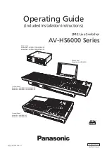
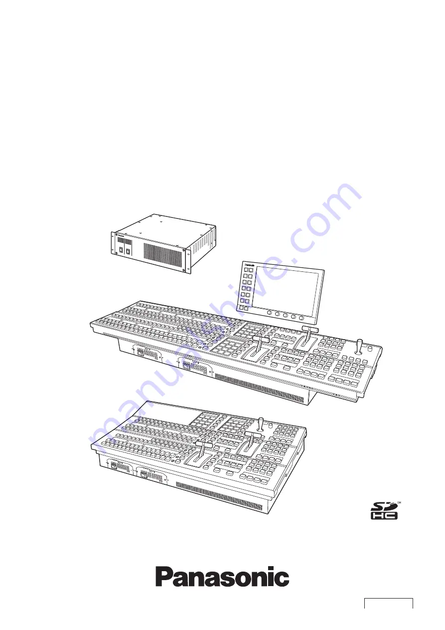
background image

2ME Live Switcher

AV-HS6000 Series

ENGLISH

VQT5J51A-4(E)

W0214HM4066 -YI

Main Frame

Model No. AV-HS60U1P/AV-HS60U2P

Model No. AV-HS60U1E/AV-HS60U2E

Menu Panel

Model No. AV-HS60C3G

Control Panel

Model No. AV-HS60C1P/AV-HS60C2P

Model No. AV-HS60C1E/AV-HS60C2E

Control Panel

Model No. AV-HS60C4P

Model No. AV-HS60C4E

(Included Installation Instructions)

Operating Guide

Summary of Contents for AV-HS60C1E

Page 1: ...rame Model No AV HS60U1P AV HS60U2P Model No AV HS60U1E AV HS60U2E Menu Panel Model No AV HS60C3G Control Panel Model No AV HS60C1P AV HS60C2P Model No AV HS60C1E AV HS60C2E Control Panel Model No AV HS60C4P Model No AV HS60C4E Included Installation Instructions Operating Guide ...

Page 2: ...ws of the software provided with this unit are expressly prohibited How to read this document r r Abbreviations The following abbreviations are used in this document f f Microsoft Windows 7 Professional SP1 32 64 bit is abbreviated to Windows 7 f f Windows Internet Explorer 8 0 Windows Internet Explorer 9 0 and Windows Internet Explorer 11 0 are abbreviated as Internet Explorer f f The model numbe...

Page 3: ...nd transition 55 Selecting the wipe direction 55 Wipe decorations border soft effect 55 Modifying wipe 56 KEY 61 Selecting the key type 61 Selecting the key source 62 Key transitions 62 Key wipe transition 63 Key output 65 Adjusting the luminance key linear key 65 Adjusting the chroma key 65 Key decorations 70 Masking the key signals 71 Setting box matte 71 PinP Picture in Picture 71 Setting the p...

Page 4: ...S60C2 AV HS60C4 151 Settings for the main control panel and sub control panel 151 Setting the button color 151 Setting the external connection 153 Setting a serial port 153 Setting a tally 153 Setting the GPI input output 154 Maintenance settings 156 Software and hardware version 156 Alarm 156 Initialization 157 Installation condition of the Storage Module 158 Maintenance 159 Setting the date and ...

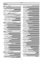
Page 5: ...Please read this chapter and check the accessories before use Chapter 1 Overview ...

Page 6: ... anti spyware program etc The following points should be borne in mind as well f f Use with the same segment is recommended for the devices which are connected to the unit If the unit is connected to the devices whose segments are different events dependent upon the settings inherent to the network equipment for instance may occur Thoroughly check the connections with the devices to which the unit...

Page 7: ...ed with 4 channels per ME total 8 channels of keyer which is capable of PinP f f The unit is equipped with 4 channels of downstream keyers f f The unit is equipped with 4 channels of upstream keyers Primatte is a registered trademark of IMAGICA DIGIX Inc The copyrights of Primatte belong to IMAGICA DIGIX Inc The patents for Primatte belong to IMAGICA DIGIX Inc r r MultiViewer output f f The unit i...

Page 8: ...HS60C2P 2 cables AV HS60C1E 2 cables AV HS60C2E 4 cables f f LAN cable 1 cable used to connect with the Main Frame AV HS60U1 AV HS60U2 f f Switch blank cap large 24 caps f f Switch blank cap small 12 caps f f AV HS60C1 AV HS60C2 Operating Instructions r r Control Panel AV HS60C4 f f AC cable AV HS60C4P 2 cables AV HS60C4E 4 cables f f LAN cable 1 cable used to connect with the Main Frame AV HS60U1...

Page 9: ...ditions CPU Intel CoreTM 2 DUO 2 4 GHz or more recommended Memory 2 GB or more recommended Network function 100Base TX Image display function Resolution 1024 768 pixels or more Color generation True Color 24 bits or more Compatible OS Microsoft Windows 7 Internet Explorer 9 0 Internet Explorer 11 0 f f Internet Explorer 8 0 cannot be used Hard disk drive 50 MB or more free memory Other Adobe Reade...

Page 10: ...l being r r Built in display Leaving the organic EL panel of the source display panel multi selection menu panel and LCD panel of the Menu Panel AV HS60C3 on with the same image over a long period of time may result in afterimage burn in Use after configuring the screensaver settings The liquid crystal parts are highly precise with more than 99 99 of the pixels effective This leaves less than 0 01...

Page 11: ...This chapter describes installation and connection Chapter 2 Installation and Connection To installation personnel ...

Page 12: ... and the power supply 2 or when the power switch is set to OFF An alarm will not be displayed on the Main Frame AV HS60U1 because it has only the power supply 1 r r Handle carefully f f Dropping the unit or subjecting it to strong impact or vibration may cause trouble and or malfunctioning r r Do not allow any foreign objects to enter inside the unit f f Allowing water metal items scraps of food o...

Page 13: ...f Secure a space surrounding the ventilation holes on the front panel of the power supply unit and on the rear panel of the Control Panel AV HS60C1 AV HS60C2 AV HS60C4 so that air circulation is not impeded In particular ensure sufficient space between ventilation and wiring when using mounted in a panel or table f f Avoid installing the unit where it will be exposed to direct sunlight or to the h...

Page 14: ...activation operation is performed using the key code attached to the Chromakey Software AV SFU60 optional chroma key functions of KEY2 KEY3 and KEY4 can be added One package contains a single keyer for ME1 and ME2 so three packages are required when adding chroma key functions to all keyers For details refer to Expansion of the chroma key function page 158 ...

Page 15: ...nect the switcher output signal to monitors and other external devices HD SDI monitor REF terminal Connect the system sync signal from the sync signal generator The loop through output is performed in the external sync mode If the loop through output is not going to be used provide a 75 Ω termination Black burst signals are output from both terminals in the internal sync mode Internal sync mode In...

Page 16: ...DEL MIX 02s01f MIX 01s00f MIX 01s00f WIPE 01s00f CHR LIN FULL FULL WIPE 01s00f MIX 01s00f MIX 01s00f MIX CG5V CG6V CAM1 CAM2 CG5V CG6V CAM1 CAM2 CG1V CG2V CG3V CG4V 01s00f MIX ME2 01s00f MIX ME1 01s00f BUS SHFT BUS SHFT 1 7 4 1 1 8 1 9 SHOT000 1 1 SHOT001 1 2 SHOT002 1 3 SHOT003 1 4 1 5 1 6 PLAY SEL AUK DSK ME2 XPT ME1 4 SDI IN3 3 SDI IN2 2 SDI IN1 1 Black 24 23 22 21 20 19 18 17 16 15 14 13 12 11...

Page 17: ... IN3 3 SDI IN2 2 SDI IN1 1 Black 24 23 22 21 20 19 18 17 16 15 14 13 12 11 10 SDI IN9 9 SDI IN8 SDI IN11 SDI IN12 Still 1V Still 2V Still 3V Still 4V Clip 1V Clip 2V Clip 3V Clip 4V CBGD 1 ME1 PGM ME2 PGM SDI IN10 8 SDI IN7 7 SDI IN6 6 SDI IN5 5 SDI IN4 4 3 4 2 4 4 4 6 4 5 4 7 4 9 4 8 OP STILL1 Computer Main control panel f f Computer settings The IP address of the computer to connect is set to a ...

Page 18: ...rsonnel r r Serial port Connect the serial ports RS 422 4 of the Main Frame AV HS60U1 AV HS60U2 or the serial ports RS 422 1 RS 232 1 of the Control Panel AV HS60C1 AV HS60C2 AV HS60C4 to external devices f f It supports plug in software f f The serial port cannot be used with the sub control panel ...

Page 19: ...This chapter describes the names functions and operations of each part of the unit Chapter 3 Part Names and Functions ...

Page 20: ...supply model AV HS60U1 does not have the POWER switch for the power supply 2 f f When turning off the power of the redundant power supply model AV HS60U2 set both POWER switches for the power supply 1 and the power supply 2 to OFF NOTE t t When an alarm has occurred stop using the unit immediately and be sure to contact your dealer Rear panel 1 3 4 5 6 7 8 9 10 11 12 14 2 13 1 SDI IN 1 to SDI IN 3...

Page 21: ...Equipped with 18 contact input ports GPI IN that control the unit externally and an alarm output port ALARM OUT page 170 11 GPI OUT1 GPI OUT2 terminals connector D sub 25 pin female 2 inch screw signal GPI OUT Equipped with 48 output ports GPI OUT that output tallies and status information from the unit page 169 12 SIGNAL GND terminal signal SG Connects to the ground of the system 13 F1 F2 termina...

Page 22: ...8 SDI IN11 SDI IN12 Still 1V Still 2V Still 3V Still 4V Clip 1V Clip 2V Clip 3V Clip 4V CBGD 1 ME1 PGM ME2 PGM SDI IN10 8 SDI IN7 7 SDI IN6 6 SDI IN5 5 SDI IN4 4 3 4 2 4 4 4 6 4 5 4 7 4 9 4 8 OP STILL1 1 2 3 4 5 r r AV HS60C4 CHR LIN LUM FULL 4 SDI IN3 3 SDI IN2 2 SDI IN1 1 Black 16 15 14 13 12 11 10 SDI IN9 9 SDI IN8 SDI IN11 SDI IN12 Still 1V Still 2V Still 3V SDI IN10 8 SDI IN7 7 SDI IN6 6 SDI ...

Page 23: ...osspoint link coupling function page 134 KEY1 F S to KEY4 F S buttons Switches to the source selector buttons for the key fill buses or key source buses f f If you select key fill signal or key source signal using the KEY bus crosspoint buttons the signals are linked and another signal is automatically selected The unit s linking operation has two modes The mode setting can be made from the CONF b...

Page 24: ... buttons f f The pages of the buses included in the corresponding ME can be switched at once To switch pages at individual buses assign the 2nd PAGE 3rd PAGE button to the KEY bus crosspoint buttons PGM A bus crosspoint buttons and the PST B bus crosspoint buttons page 131 Button status Displayed page 2nd PAGE button 3rd PAGE button Off Off First page Lit Off Second page Off Lit Third page Lit Lit...

Page 25: ...ion tab Trans Type column when the NAM button is on For details refer to NAM button setting page 54 WIPE button Performs transition according to the patterns set in the menu or selected at the wipe preset on the multi selection panel area EMEM LINK button Performs transition according to the patterns registered in the event memory page 92 6 ME CHG button Switches the display of the multi selection...

Page 26: ...ry Switches target to be displayed in the SEL KEYPVW output page 150 2 Key DSK preset memory buttons 1 2 3 4 Recalls stores the key preset memory page 102 f f Short press Recalls data saved to the corresponding button Recall f f Long press Stores the current key settings to the corresponding button Store Current key setting can be deleted Delete by press and holding For details refer to Key preset...

Page 27: ...ry cards Memory cards used with the unit should conform to SD or SDHC standards Be sure to format memory cards using the unit Memory cards with the following capacity can be used for the unit The unit does not support SDXC memory cards SD memory card 8 MB to 2 GB SDHC memory card 4 GB to 32 GB For the latest information not available in the Operating Guide visit the following website http pro av p...

Page 28: ...nding terminal Connect to a 3 pin power outlet which is equipped with a grounding terminal f f If a 3 point power outlet is not available be sure to consult your dealer 2 MAIN FRAME terminal connector RJ 45 signal 100Base TX Connects to the PANEL terminal or LAN terminal of the Main Frame AV HS60U1 AV HS60U2 f f When connected to the LAN terminal no video will be displayed on the Menu Panel AV HS6...

Page 29: ...rt ALARM OUT page 170 10 F1 F2 terminals Fuse 11 SIGNAL GND terminal signal SG Connects to the ground of the system NOTE t t For the cable connecting to the DVI D terminal use a double shielded cable t t For the cable connecting to the MAIN FRAME terminal COM1 M COM2 RS 232 terminal and GPI I O terminal use a shielded cable t t The COM1 M terminal and the COM2 RS 232 terminal cannot be used with t...

Page 30: ...d the numeric values of the number button focused on the menu can be changed When the rotary encoder is double clicked or held down the numeric values of the number button focused on the menu will return to the default settings Split display of the menu screen 1 2 MENU MODE button MENU MODE button WFM VECT button PICT VECT PICT WFM 1 MENU MODE button Each time this button is pressed the full scree...

Page 31: ...ected using the SYS button SYSTEM Display tab Video Codec column Target item the image selected in the DISP bus the WFM or the VECTOR is not displayed t t Image WFM and VECTOR are not displayed on a computer connected to the LAN terminal of the Main Frame AV HS60U1 AV HS60U2 t t Image WFM and VECTOR are not displayed in the Menu Panel AV HS60C3 connected to the sub control panel Rear panel 1 1 CON...

Page 32: ...This chapter describes basic operations and matters to be performed prior to use Chapter 4 Preparations ...

Page 33: ...in Frame The firmware of the Control Panel is updated when the following operation is performed Once the update is correctly performed the firmware version of the Control Panel will match with the firmware version of the Main Frame and it will boot in normal status RECALL STORE DEL CHR LIN FULL FULL WIPE 01s00f MIX 01s00f MIX 01s00f MIX CG5V CG6V CAM1 CAM2 01s00f MIX ME2 01s00f BUS SHFT 4 1 4 3 4 ...

Page 34: ...10 00 0 00 Turning power off 1 Set the POWER switches of the Main Frame AV HS60U1 AV HS60U2 and the Control Panel AV HS60C1 AV HS60C2 AV HS60C4 to OFF f f For the redundant power supply model AV HS60U2 AV HS60C2 AV HS60C4 set both POWER switches of the power supply 1 and the power supply 2 to OFF f f The power indicator will go off when power is cut off NOTE t t Do not turn off the power when acce...

Page 35: ... the menu When items you want to set are not displayed move the scrollbar to display them 3 ALARM When an alarm has occurred the ALARM indicator area will light up red If ALARM is selected the same page as displayed with the SYS button on the top menu MAINTENANCE Alarm tab will appear 4 MACRO The status for the MACRO indicator is as follows f f Lights up red during macro recording f f Lights up gr...

Page 36: ...entry items are selected the on screen numerical keypad appears If set the values and closed the keypad the numeric values set for the items and the numeric bar will be displayed The contents displayed on the screen will differ depending on the item to be input such as time r r On screen numerical keypad 3 4 5 6 7 1 2 8 13 9 10 11 12 1 Entry field The entered numeric values are displayed After sel...

Page 37: ...AV HS60C4 If the numeric entry item or title area of the column is selected the corresponding column will become a selected state focus state When the column is in a focus state numeric values can be changed by turning the dial of the rotary encoder corresponding to the item to be set The three items from the left of the column can be operated using the positioner of the positioner area X axis Y a...

Page 38: ... f Select Color Palette in the same column as Hue Sat and Lum and use the color palette screen r r Color palette screen 5 1 2 3 4 6 7 9 8 1 New Displays the colors being changed on the color palette screen 2 Default Displays 8 default colors The same colors are set when selected 3 Hue Pad Tap any color to set hue Vertical axis Color tone Hue 4 Sat Lum Pad Tap any color to set saturation and lumina...

Page 39: ... the item is selected the screen closes and the item is displayed at the lower part of the list box Depending on the function after selecting the item select OK to close the screen Radio button Select an item from multiple options Check button Set items to on off On and off will switch whenever selected ...

Page 40: ...60C4 page 137 Background wipe preset menu Press the BKGD WIPE button on the multi selection panel area to display the background wipe preset menu Nine background wipe preset patterns can be stored for each ME The wipe setting used in the corresponding ME is always stored to the pattern button selected in the pattern selection menu If another pattern button is selected the wipe pattern and setting ...

Page 41: ...EL Moves to the TARGET SELECT menu 1 9 Register memory for operation target Selects the register memory for the operation target Shows the shot memory name on the upper line and the shot memory number on the lower line 10 RECALL STORE DEL Switches the operation mode 11 PAGE SEL Moves to the PAGE SELECT menu 12 r r TARGET SELECT menu Select SEL in the operation menu of the register memory to displa...

Page 42: ...Lights up when CLIP or CBGD is selected in the TARGET SELECT menu S3 SEL Moves to the TARGET SELECT menu 1 9 Register memory for operation target Selects the register memory for the operation target Page numbers sub numbers etc are displayed in each item 10 11 PAGE SEL Moves to the PAGE SELECT menu 12 PLAY Starts playback when awaiting or pausing playback r r TARGET SELECT menu Select SEL in the o...

Page 43: ...t Page numbers sub numbers etc are displayed in each item 10 RECALL STORE DEL Switches the operation mode 11 PAGE SEL Moves to the PAGE SELECT menu r r PLAY menu only when operating CLIP1 to CLIP4 Select PLAY in the OPERATION SELECT menu to display the PLAY menu S1 CLIP1 CLIP4 Moves to the CHANNEL SELECT menu f f Among CLIP1 to CLIP4 the buttons for the operation target will be displayed S2 Curren...

Page 44: ...e register memory to display the OPERATION SELECT menu S1 S3 OPERATION SELECT Displays the menu title 1 REG SEL Moves to the operation menu for the register memory 2 PLAY Moves to the PLAY menu f f Operations are impossible for STILL1 to STILL4 3 REC Moves to the REC menu 11 EXIT Returns to the original menu r r PAGE SELECT menu Select PAGE SEL in the operation menu of the register memory to displ...

Page 45: ... menu IMAGE BKGD tab B Effect1 column CBGD1 CBGD2 The DSK MISC button on the top menu CBGD CBGD1 CBGD2 tab Main Color column DSK1 F S DSK4 F S The DSK MISC button on the top menu DSK1 to DSK4 Setting tab DSK Adjust column VMEM F S The MEM button on the top menu STILL Still tab DISP Switches to the split display in which the image selected in the DISP bus and the WFM VECT are displayed STILL1 V K S...

Page 46: ... 46 Chapter 4 Preparations Menu delegation function Can be used when assigned to the PGM A bus crosspoint buttons or PST B bus crosspoint buttons ...

Page 47: ...60C2 AV HS60C4 main control panel to the PANEL terminal of the Main Frame AV HS60U1 AV HS60U2 Connect the second and subsequent Control Panel AV HS60C1 AV HS60C2 AV HS60C4 sub control panel to the LAN terminal of the Main Frame AV HS60U1 AV HS60U2 It is necessary to change the network setting of sub control panel before connecting f f The default setting is as follows IP address 10 0 0 2 subnet ma...

Page 48: ...address set for the LAN terminal of the Main Frame AV HS60U1 AV HS60U2 t t If the default setting for the LAN terminal of the Main Frame AV HS60U1 AV HS60U2 is not changed it can be connected as the sub control panel when the value described in the setting example is set t t For details on the network setting for the LAN terminal of the Main Frame AV HS60U1 AV HS60U2 refer to Configuring the netwo...

Page 49: ...e frame synchronizer freeze effects and frame delays Status tab Displays the information on the images for SDI input signals Up Converter tab Make the settings for built in up converters at the SDI IN 27 SDI IN 28 SDI IN 31 SDI IN 32 column 2 Select the IN OUT button DVI IN Frame Buffer Status tab and make the following settings Frame Buffer tab Make the settings for DVI D input signals Status tab...

Page 50: ...tab and make the following settings Assign tab Assigns output matrix Down Converter tab Makes the settings for down converters built into the SDI OUT 14 SDI OUT 16 terminals 2 Select the IN OUT button C C OUT SDI OUT 13 to SDI OUT 16 tabs and make the color corrector settings f f Make the settings for color correctors built into the SDI OUT 13 to SDI OUT 16 terminals f f For details on the setting...

Page 51: ...ng disabling of each tally group GPI OUT tab Assigns source tally outputs by tally group Setting date and time Set the date and time to be used as a timestamp when saving files to the memory card or the Storage Module AV HS60D1 optional It can also be displayed on the split screen of the MultiView display 1 Select the SYS button MAINTENANCE Misc tab 2 Set the date and time in the Date Time LTC col...

Page 52: ...This chapter describes menu operations Chapter 5 Basic Operations ...

Page 53: ... the A B bus system or the flip flop system PGM PST system 1 Select the CONF button OPERATE Transition tab 2 Set an item in Bus Mode Type in the Bus Mode column Common Set the same bus mode in ME1 and ME2 Setting of the Bus Mode column Bus Mode is applied to both ME1 and ME2 Each Different bus modes can be set for ME1 and ME2 Settings of the Each Bus Mode1 column Bus Mode ME1 and Bus Mode ME2 are ...

Page 54: ...er the start point of the manual transition or the auto transition when a value larger than 0 is set for Start Point At this time the lamp for start point of the fader lever will blink in the transition status display End Point Sets the end point for background transition The background transition will complete before the end point of the manual transition or the auto transition when a value large...

Page 55: ...It is making so the shape does not change when the transition amount is in the range of 40 to 60 Selecting the wipe direction Press a wipe direction selection button to select the wipe direction for the background transition For details refer to Transition area page 25 r r Fader lever operations and wipe directions when WIPE 7 is selected as a wipe pattern A B B A B A B A B A A B A B A B N button ...

Page 56: ...Palette in the Border Color column Setting the background image f f Set the background image when the following pattern waveforms are selected SQ 47 49 51 52 53 114 f f The background image is output only when 4 3 or 4 3 Smooth is selected on the top menu ME1 ME2 button BKGD Position tab Trim column Trim when SQ is set to 47 or 49 1 Select the ME1 ME2 button BKGD Edge Border tab 2 Set Base Video i...

Page 57: ...s selected as the system format 2 Enabled when the following pattern waveforms are selected SQ 41 51 54 3 Select an item in Manual in the Trim column Free Sets the amount of trimming for Left Right Top and Bottom separately Pair Changes the settings in such a way that the Left and Right trimming amounts and the Top and Bottom trimming amounts are the same This makes for a top bottom and left right...

Page 58: ...e Spin column Off Does not spin regardless of setting value of X Spin Y Spin and Z Spin Trans Spin Spins in specified amount of spin depending on the transition Auto Spin Spins in speed in accordance with specified amount of spin regardless of the transition Manual Spin Tilts in specified amount of spin regardless of the transition It may become discontinuous at the edge of transition in the Auto ...

Page 59: ...ages in the PGM bus and the PST bus using 1ch of DVE f f 3D 114 Free D DVE Combines the images in the PGM bus and the PST bus using 2ch of DVE The transition amount by the AUTO button or the fader lever is disabled when these waveforms are selected and the WIPE button is pressed 1 Press the WIPE button 2 Select the ME1 ME2 button BKGD BKGD Pattern tab 3 Set an item in Pattern of the BKGD Pattern c...

Page 60: ...using the free pattern Examples of registration of the event memory using the Free D DVE pattern are described Fader Prio INV CH1 PGM CH2 PST Description Event 1 R mid position PGM Off Full size Arbitrary Event 2 R mid position PGM PST Background On Arbitrary Arbitrary Changes the priority and bring CH2 PST to front Event 3 R mid position PST On Arbitrary Full size ...

Page 61: ...ls It is used when the key source signal and key fill signal are different Use source with a black background and white characters or shape to be combined by the key as the key source signal Source which is not black and white may not be combined clearly Source with white background and black characters can be used by inverting the keys with the key invert function Chroma chroma key Creates key si...

Page 62: ...ime the KEY but selector buttons light in Low tally color Key source signal When the KEY bus selector buttons are pressed while the BUS SHFT button is held down the KEY bus selector buttons light in the Preset tally color and key source different from the link setting can be selected using the KEY bus crosspoint buttons The changed key source is not stored as the link setting and the source return...

Page 63: ...d transition time of respective keys which have been set on the menu The KEY1 TRNS to KEY4 TRNS buttons flicker during key in and light when the transition is complete If the KEY1 TRNS to KEY4 TRNS buttons are pressed while key in is complete transition of the key image key out is executed The KEY1 TRNS to KEY4 TRNS buttons light during key out and go off when the transition is complete If the KEY...

Page 64: ... be divided to the specified number f f Enabled when the following pattern waveform is selected WIPE 1 Select the ME1 ME2 button KEY1 to KEY4 Modify tab 2 Set the specification method of the number of division in H V Sync of the Multi column On Makes the number of division the same in horizontal and vertical directions Off Different number of division can be specified for horizontal and vertical d...

Page 65: ...d f f ME1CLN ME2CLN Outputs clean signals before adding key effects These can also output key out signals used for key compositions f f SEL KEYPVW Outputs the preview of the key relevant to the operation of KEY1 to KEY4 buttons in the KEY operation section of each ME and DSK1 to DSK4 buttons To switch the screen to the preview screen for chroma key adjustment of the relevant keyer use the ME1 ME2 ...

Page 66: ...sets the reference color background color for extracting the foreground image from the key source 5 Set X Pos Y Pos and Size in the Sample Area column f f Set the position and size of the sample marker 6 After setting the sample area select Sampling in the Sample Area column f f The area that has been set is now sampled f f If you select Undo in the Sample column after sampling is executed the sta...

Page 67: ...in the background image and Removing noise in the foreground image there will still be some color irregularity in detail areas such as around hair in the following image This step removes the color irregularity remaining in the detail areas 1 Select the ME1 ME2 button KEY1 to KEY4 Chroma tab 2 Select Composite in View in the Sample column f f The image for the chroma key preview becomes a composit...

Page 68: ...oise refer to Removing noise in the background image page 66 f f For details on Clean FG Noise refer to Removing noise in the foreground image page 67 f f For details on Spill Sponge refer to Removing color irregularity in the detail areas page 67 r r Matte Sponge Select the semi transparent parts of the subject in the foreground image and make them matte non transparent Matte Sponge makes the sem...

Page 69: ...ans Trans 8 Set Detail in the Fine Tuning column f f Adjust the matte information for the color close to the color of the background image This is useful when restoring the details of an image such as stray hairs or smoke which have been lost in the foreground image as a result of sampling Detail Detail Fine tuning the generated chroma key signals Fine tune generated chroma key signals 1 Select th...

Page 70: ... Fig 1 Off Does not add an edge Border Adds a border around the entire edge Drop Adds a diagonal border Shadow Adds a shadow Outline Adds an outline only a border with no fill 3 Set Width in the Edge column f f Set the edge width 4 Select an item in Direction in the Edge column Fig 2 f f Set the direction to add Drop or Shadow effect in 45 increments 5 Set Density in the Edge column f f Set the ed...

Page 71: ...t the mask signal 5 Set Left Top Right and Bottom in the Mask Adjust1 Mask Adjust2 column f f Set the area to be masked The Left setting cannot exceed the Right setting and vice versa and the Top setting cannot exceed the Bottom setting and vice versa Left Masks the key left position Top Masks the key top position Right Masks the key right position Bottom Masks the key bottom position Setting box ...

Page 72: ...ion column f f Set the PinP size f f Up to 400 can be set for KEY1 and KEY2 100 or above setting is disabled when an item other than Off is selected in WipeMask in the Mode column f f Up to 100 can be set for KEY3 and KEY4 4 Set X Y and Z in the Rotation column f f Set the tilt for the PinP image f f This setting is available only for KEY1 and KEY2 f f X and Y will be disabled when anything other ...

Page 73: ...ync column Normal operation may not be performed if set each other PinP decorations Add a border or soft effect to PinP 1 Select the ME1 ME2 button KEY1 to KEY4 PinP Adjust tab 2 Select an item in Border in the Border column Off Does not add the border effect On Adds the border effect 3 Set Width in the Border column f f Sets the border width 4 Set Soft in the Border column f f Sets the amount of ...

Page 74: ...m column f f The aspect ration of the wipe pattern is changed when anything other than Off is selected in WipeMask in the Mode column Copying the PinP setting The setting for PinP can be copied 1 Select the ME1 ME2 button MISC Misc tab 2 Select an item in Key1 From to Key4 From in the PinP Copy column f f Select the channel of the key to be the copy source of the PinP setting 3 Select Execute in t...

Page 75: ... 4th Key3 2nd 3rd Key4 1st 2nd Setting Key On Link Combine Key1 to Key4 in the same ME to start transitions simultaneously 1 Select the ME1 ME2 button MISC Misc tab 2 Select an item in Key1 to Key4 in the Key On Link column f f Select Off or On for any key Example When Key1 and Key3 are set to On and Key2 and Key4 are set to Off Pressing the KEY1 TRNS button starts transitions of Key1 and Key3 at ...

Page 76: ... Key in the DSK column Chroma Off Generates the key signals only from the luminance components Chroma On Generates the key signals considering the chrome components in addition to the luminance components This item is set when a low luminance component color is used for key signals such as when cutting blue characters 4 Select an item in Clean Key in the DSK column Off Cuts key fill with a key sig...

Page 77: ...becomes the same as the Out Type column setting DSK output The DSK block outputs the following signals For details refer to System Menu page 140 f f DSKPGM1 DSKPGM2 Outputs program signals of DSK compositions Select the SYS button on the top menu MAIN FRAME DSK tab Config column DSK1 to DSK4 and set them to either DSKPGM1 or DSKPGM2 to assign the signal to one of the outputs f f DSKPVW1 DSKPVW2 Ou...

Page 78: ... Edge column f f Set the edge width 4 Select an item in Direction in the Edge column Fig 2 f f Set the direction to add Drop or Shadow effect in 45 increments 5 Set Density in the Edge column f f Set the edge density Setting the DSK edge fill Set the source to be inserted as an edge 1 Select the DSK MISC button DSK1 to DSK4 Setting tab 2 Set Fill in the Edge column Matte Uses the color set in the ...

Page 79: ...ert in the Mask column Off Does not invert the mask signal On Inverts the mask signal 5 Set Left Top Right and Bottom in the Mask Adjust1 Mask Adjust2 column f f Set the area to be masked The Left setting cannot exceed the Right setting and vice versa and the Top setting cannot exceed the Bottom setting and vice versa Left Masks the key left position Top Masks the key top position Right Masks the ...

Page 80: ...ssing the DSK1 TRNS button starts transitions of DSK1 and DSK3 at the same time On off of the DSK by the menu operation Each DSK can be turned on off with the cut transition by the menu operation 1 Select the DSK MISC button MISC Misc tab 2 Select an item in DSK1 to DSK4 in the DSK ON column Off The DSK is turned off On The DSK is turned on NOTE t t The button operation toggle operation is recorde...

Page 81: ...gnals do not change even when the key source signals are switched Linear linear key Creates key signals from luminance components of key source signals It is used when the key source signal and key fill signal are different f f Use source with a black background and white characters or shape to be combined by the key as the key source signal Source which is not black and white may not be combined ...

Page 82: ...ignal list on the right column f f Signals available on the USK bus are as follows Signal name Description of signal SDI IN1 SDI IN32 SDI input signals 1 to 32 DVI IN1 DVI IN2 DVI D input signals Still 1V Still 2V Still 3V Still 4V Video memory still image 1 to 4 videos Still 1K Still 2K Still 3K Still 4K Video memory still image 1 to 4 keys Clip 1V Clip 2V Clip 3V Clip 4V Video memory moving imag...

Page 83: ...Select an item in Invert in the Key Adjust column Off Does not invert the key signals generated internally On Inverts the key signals generated internally Masking the USK Mask the key signals using the mask signal of the box pattern The following figure is the status when Type is set to ForeGround and Invert is set to Off Area where the key signal is effective Video signal range Area masked Right ...

Page 84: ... 84 Chapter 5 Basic Operations USK Upstream key Left Masks the key left position Top Masks the key top position Right Masks the key right position Bottom Masks the key bottom position ...

Page 85: ...t2 B Effect2 column On Enables the monochrome color effect Off Disables the monochrome color effect 3 Set Mono Hue and Mono Sat in the Effect2 A Effect2 B Effect2 column Hue Adjusts the hue of the monochrome color effect Sat Adjusts the saturation of the monochrome color effect Mosaic defocus effect Add the mosaic or defocus effect to an image 1 Select the ME1 ME2 button IMAGE Key1 Key2 BKGD tab 2...

Page 86: ... Gray L Tone3 Gray H Tone4 White column RGB Matrix Initializes the setting values in the Matrix R G Matrix B column All Initializes all 3 Select Initialize in the Setting column f f The corresponding item is initialized Copying the setting 1 Select the IN OUT button C C IN 25 30 C C IN 31 32 C C OUT the tab to be set f f Select the tab to be set from the SDI IN 25 tab to SDI IN 32 tab or the SDI O...

Page 87: ...of the Tone1 Black Tone2 Gray L Tone3 Gray H Tone4 White column independently from RGB On Uses the value of Red as the values of Green and Blue for the Tone1 Black Tone2 Gray L Tone3 Gray H Tone4 White column NOTE t t The unit simply connects the set black level gray Low level gray High level and white level to create a tone curve Depending on the setting values the tone curve might not be as desi...

Page 88: ...f Does not add the gradation effect 3 Select an item in Color Type in the Wash column Dual Adds the two color gradation effect set in the Main Color and Sub Color columns Rainbow Adds the rainbow color gradation effect 4 Adjust the color f f When Dual is selected set Hue Sat Lum or Color Palette in the Sub Color column f f When Rainbow is selected set Rainbow Sat and Rainbow Lum in the Wash column...

Page 89: ...ge 1 to 4 keys Clip 1V Clip 2V Clip 3V Clip 4V Video memory moving image 1 to 4 videos Clip 1K Clip 2K Clip 3K Clip 4K Video memory moving image 1 to 4 keys CBGD1 CBGD2 Color background 1 2 CBAR Color bar Black Black image ME1PGM ME2PGM Program video signal ME1PVW ME2PVW Preview video signal ME1CLN ME2CLN Clean signal ME1KEYPVW ME2KEYPVW Key preview video signal DSKPGM1 DSKPGM2 Program video signa...

Page 90: ...ing the target NOTE t t A registered register memory can be overwritten Recalling register memories of the shot memory playback Recall the image effect settings registered in the register memory 1 Select the MEM button SHOT MEMORY Register tab 2 Select Recall in the Register column f f The Recall screen is displayed ME1 ME2 DSK AUX CBGD XPT Select the target to recall View Select the display mode ...

Page 91: ... mode is not possible for playback of ME1 or ME2 in the 3G mode or the 4K mode when the selection for playback is not selected at the time of registration Editing register memories of the shot memory Delete a registered register memory or change file names 1 Select the MEM button SHOT MEMORY Register tab 2 Select Misc in the Register column f f The Misc screen is displayed Rename Select Rename aft...

Page 92: ...GD BKGD BKGD Key1 Key2 Key3 Key4 ME2 Key1 Key2 Key3 Key4 Key1 Key2 Key3 Key4 1 Select the MEM button SHOT MEMORY Detail Select tab 2 Select an item in BKGD Key1 to Key4 in the Detail ME column On Sets as a memory target Off Does not set as a memory target 3 Select an item in A B XPT Key XPT in the Detail XPT column On Sets as a memory target Off Does not set as a memory target 4 Select an item in ...

Page 93: ...ory to be played and the transition target do not overlap register memory playback and transition each works independently When the register memory to be played and the transition target overlap register memory playback is prioritized r r Timeline A timeline is a group of events which have been placed on the time axis r r Event points and edit points On a timeline the position where an event has b...

Page 94: ... back at the mark position during event playback The Clip mark appears on the timeline GPI Out When EMEM 01 to EMEM 20 are selected and the mark is registered in the event point pulse signals are output from the GPI output port to which EMEM 01 to EMEM 20 are assigned at the mark position during event playback The GPI OUT mark appears on the timeline 6 Set the transition time in Event Duration in ...

Page 95: ...int Lead Moves to the first event point Step Moves to the previous event point Step Moves to the next event point Last Moves to the last event point 5 Play a timeline in Play or Pause in the Control2 column Play Plays back an event memory Pause Stops the event memory 6 Select an item in the Edit1 column f f Add or modify events New Initializes the work memory Insert Inserts events If the edit poin...

Page 96: ... column f f Playback of event memories can be linked with the fader lever operation Off Does not play back an event memory according to the fader lever operation ME1 Plays back an event memory according to the operation of the ME1 fader lever ME2 Plays back an event memory according to the operation of the ME2 fader lever ME selected as playback target in the Select1 Select2 column is assumed by t...

Page 97: ...one of ME1 or ME2 The target selected at registration is played back in the work memory even when either ME1 or ME2 is selected at the start of playback When there is no target selected at registration ME1 recorded at registration is played back in the work memory even when either ME1 or ME2 is selected at the start of playback f f Playback of DSK CLIP AUX and CBGD The target selected at the start...

Page 98: ...GD BKGD BKGD Key1 Key2 Key3 Key4 ME2 Key1 Key2 Key3 Key4 Key1 Key2 Key3 Key4 1 Select the MEM button EVENT MEMORY Detail Select tab 2 Select an item in BKGD Key1 to Key4 in the Detail ME column On Sets as a memory target Off Does not set as a memory target 3 Select an item in A B XPT Key XPT in the Detail XPT column On Sets as a memory target Off Does not set as a memory target 4 Select an item in...

Page 99: ... 9 pages 9 can be registered in the register memory t t Each register memory of a macro has the capacity of 127 KB and can store approximately 3000 steps of operations depending on the operation t t When an operation that takes time to process is recorded next operation may not playback correctly Insert a delay between the two operations as necessary For the procedure to insert a delay refer to Re...

Page 100: ... This plays the macro in the work memory 3 Select Play Cancel in the Status column f f This suspends macro playback 4 Select Play Resume in the Status column f f The macro playback is paused if Insert Pause event is included in the recorded macro Macro playback will resume when Play Resume is pressed while paused NOTE t t After macro playback is suspended the mode changes to the macro recording mo...

Page 101: ...sses of the ME1 and the ME2 within single Control Panel AV HS60C1 AV HS60C2 AV HS60C4 1 Select the MEM button MACRO XPT Assign tab f f The macro register memories in the right column are assigned to the crosspoints in the left column Panel ID Select the target Control Panel AV HS60C1 AV HS60C2 AV HS60C4 from the MainPanel SubPanel1 or SubPanel2 Button Group Switches the page of the macro bus Assig...

Page 102: ...O Macro tab 2 Select the Play Resume button in the Status column f f The paused playback will resume Key preset It is a preset memory to store various settings for keys Operate in the KEY DSK operation area in the Control Panel AV HS60C1 AV HS60C2 AV HS60C4 Operating in the KEY DSK operation area on the Control Panel AV HS60C1 AV HS60C2 AV HS60C4 Call register delete the key preset memory with the...

Page 103: ...Still 2V Still 2K Still 3V Still 3K Still 4V Still 4K Clip 1V Clip 1K Clip 2V Clip 2K Clip 3V Clip 3K Clip 4V Clip 4K From XPT VMEM F VMEM S To XPT STILL V K 1 to 4 1 frame volatile memory CLIP V K 1 to 4 High image quality Approx 30 sec Standard image quality Approx 60 sec volatile memory Storage Module SSD Still Register Max 81 Clip Register Max 81 non volatile memory Control Panel Local compute...

Page 104: ...he Rec1 column or the time set using Limit Time in the Rec2 column has passed When the recording of the moving images is completed thumbnails of the moving images are displayed on the thumbnail screen Various settings when recording moving images Clip 1 Select the MEM button CLIP Rec tab 2 Select an item in Key Enable in the Rec1 column f f Set whether to record key signals at the same time On Rec...

Page 105: ...mn f f The Recall screen is displayed 3 Change the screen display as necessary Sort Sorts the file icon view in ascending or descending order by file number 1 file name or date View Select the display mode ALL Displays all the memory including the unregistered register memory Exist Displays only the registered register memory Page 1 Switches pages File Type 2 Select the extension to display For ST...

Page 106: ... the protection status for the corresponding file Deleting the file or changing the file name cannot be performed for the protected file Sort Sorts the file icon view in ascending or descending order by file number 1 file name or date View Select the display mode ALL Displays all the memory including the unregistered register memory Exist Displays only the registered register memory Page 1 Switche...

Page 107: ...er add four digit numbers starting with 0001 in sequence after the file name excluding the file extension in advance f f To generate a clip file with audio data save the audio file extension wav in the same folder as the folder where the TARGA files are saved At this time set the name of the audio file part excluding the extension wav same as the name of the TARGA files excluding the sequential nu...

Page 108: ...f the moving images starts f f Current Time displays the current playback position time f f When Pause is selected playback of moving images is suspended To resume playback select Play 3 Select Stop in the Play1 column f f Playback stops Moving to the first frame or last frame 1 Select the MEM button CLIP Play Clip1 to Play Clip4 tabs 2 Select Lead Last in the Play1 column Lead Moves to the first ...

Page 109: ...g image is stopped When Fader is selected in Link Target in the Play2 column When ON is selected in Reverse in the Play3 column When anything other than 1 is selected in Variable in the Play3 column r r Relationship between the amount of transition by the fader lever and Clip playback f f When Fader is selected in Link Target the following settings in the Play1 Play2 Play3 Edit column are disabled...

Page 110: ... to Still4 2 Source with key mark Indicates a source with key This mark is displayed only for sources with key r r Current icon of moving image Select the MEM button on the top menu CLIP Play Clip1 to Play Clip4 Rec tabs then the following icon is displayed at the top of the page This icon is used for playback status display and channel selection 2 3 4 1 6 7 8 9 5 1 Channel name Displays channels ...

Page 111: ...ey 5 Image file size r r Icon of a moving image file Select the MEM button on the top menu CLIP Register tab and then the following file icon is displayed on the file selection screen 1 3 5 4 2 7 6 1 Moving image file name 2 Register memory number 3 Image file size 4 Number of frames in the moving image file 5 Time stamp when saved 6 Source with audio data mark Indicates this is a source with audi...

Page 112: ...e size 3 Time stamp when saved in SD memory card Operating in the multi selection panel area Record or play back the moving image memories Clip and still image memories Still and save or recall register memories For details refer to Video memory menu page 43 ...

Page 113: ... f Register memory of shot memory Max 81 f f Key preset memory EMEM Register memory of event memory Max 81 Macro Register memory of macro memory Max 81 Still Four channels of current frame memory Clip Four channels of current frame memory Still Reg 81 still images saved in the register memory area 5 Select OK f f The project file is saved in a memory card and the Storage Module AV HS60D1 optional ...

Page 114: ...ocal computer Project files can be saved and loaded in from the internal storage of the local computer connected to the LAN terminal of the Main Frame AV HS60U1 AV HS60U2 Saving data in the local computer 1 Select the PRJ button PROJECT Local tab 2 Select without VMEM with Still with Still Clip or Save All in the Save column f f The project file extension prj is saved in an internal storage of the...

Page 115: ...ng them to a memory card operations other than switching crosspoints may be affected f f The memory card cannot be used with the sub control panel r r Data folder configuration Data is saved in the following folders on the memory card When data is to be loaded first save the data in the respective folders and then load the files f f The number of files that can be saved in each folder is limited t...

Page 116: ...xed to icon display File Type Fixed to file type Cancel Closes the Load screen 3 Select a file icon and select OK f f The file is loaded NOTE t t For details on the data save destination refer to Data folder configuration page 115 t t A file name can contain a maximum 32 characters t t The characters that can be used in a file name are single byte alphanumeric characters and single byte symbols Th...

Page 117: ... AV HS60D1 page 159 Saving and loading data in from the local computer Only the menu of the local computer connected to the LAN terminal of the Main Frame AV HS60U1 AV HS60U2 is displayed NOTE t t For details on saving and loading project files refer to Project management page 113 t t For details on saving and loading image files of the video memory Still Clip refer to Video memory page 103 ...

Page 118: ...This chapter describes the input output signal settings Chapter 6 Input Output Signal Settings ...

Page 119: ...me synchronizer function is set to Off t t The line synchronizer function automatically adjusts the input video signal phase to the horizontal sync signal phase For details refer to Setting the output phase page 141 t t The screen becomes black in the following combinations even if Acceptable is selected in FS in the SDI IN 1 to SDI IN 32 columns When the system format frequency is 59 94i 50i 29 9...

Page 120: ...umns On Freezes the input signals Off Does not freeze the input signals f f The F mark appears in front of the source name when the signals set for output of MultiView displays are frozen f f When the unit is used with the frame synchronizer function Off the output images may be disturbed when freezing is executed but the frozen images will not be adversely affected f f If the freeze setting is se...

Page 121: ...94 Hz 1080 50i 1920 1080 50 Hz 720 59 94p 1280 720 59 94 Hz 720 50p 1280 720 50 Hz NOTE t t If signals with any other resolutions or frequencies are input the signals cannot be imported correctly The output images in this case may be black or disturbed t t The DVI D IN1 DVI D IN2 terminals do not support HDCP High bandwidth Digital Content Protection Setting the scaling method 1 Select the IN OUT ...

Page 122: ...is when the connected device outputs the DVI signal in the 16 to 235 8 bit range r r List of DVI input scaling sizes DVI format Mode HD 1080i HD 720p SD NTSC SD PAL 1920 1080 1280 720 720 487 720 576 XGA 1024 768 Fit V 1440 1080 720 960 487 720 576 720 Fit H 487 720 576 720 Full 1920 1080 720 1280 487 720 576 720 SXGA 1280 1024 Fit V 1350 1080 720 900 487 675 576 675 Fit H Full 1920 1080 720 1280 ...

Page 123: ...1080 1280 720 720 487 720 576 WSXGA 1680 1050 Fit V 1728 1080 720 1152 Fit H Full 1920 1080 720 1280 487 720 576 720 UXGA 1600 1200 Fit V 1440 1080 720 960 487 720 576 720 Fit H 487 720 576 720 Full 1920 1080 720 1280 487 720 576 720 WUXGA 1920 1200 Fit V 1728 1080 720 1152 Fit H Full 1920 1080 720 1280 487 720 576 720 ...

Page 124: ...heck the SDI IN 1 to SDI IN 32 columns Format Displays the input format When there is no input signal No signal is displayed For formats that are not supported Undefined is displayed If horizontal pixels are the same false detection may occur Audio Displays the presence or absence of audio packets in the audio channels 1 to 8 audio packet is present t audio packet is absent Ex When only channels 1...

Page 125: ...e added ME1CLN and ME2CLN signals can be switched to the Key Out signals which are used for key combination MV1 MV4 Outputs the MultiView display signal Multiple input and output signals are reduced and output to a single screen page 127 ME1KEYPVW ME2KEYPVW SEL KEYPVW Outputs the preview signal exclusively for the key ME1PVW ME2PVW Outputs the preview signals for BKGD KEY1 to KEY4 which were selec...

Page 126: ...0H 75H When the system format is 1080 59 94i the image is delayed from the system image HD by 90H and output When the system format is 720 59 94p the image is delayed from the system image HD by 90H 1F and output When the system format is 1080 50i the image is delayed from the system image HD by 75H and output When the system format is 720 50p the image is delayed from the system image HD by 75H 1...

Page 127: ...SDI IN1 to SDI IN32 DVI IN1 to DVI IN2 Still 1V to Still 4V Still 1K to Still 4K Clip 1V to Clip 4V Clip 1K to Clip 4K CBAR Black CBGD1 CBGD2 is selected the source name set from the CONF button SOURCE NAME Panel Name MV Name tab is displayed If the input signal is selected in the AUX bus AUX1 to AUX16 the first 4 letters of the source name are displayed in When SDI IN1 source name CAM1 is selecte...

Page 128: ...he right Channel 2 of group 1 1 Select the MV button MV1 4 MV1 to MV4 tabs 2 Select an item in Level Meter in the Display column Off Does not display the level meter On Displays the level meter Setting the input signal mark The status of the input signals can be displayed in front of the source names displayed on the split screens f f F mark Indicates that the input signals are frozen f f mark Ind...

Page 129: ...This chapter describes how to operate the CONFIG menu displayed when the CONF button is pressed Chapter 7 CONFIG Menu ...

Page 130: ...C4 is connected r r Target button block for Button Group Group Select Bus Select operations f f The macro bus is not included in the target Item Description Button Group Filters the button block list in the left column All All XPT Page1 First page of the crosspoint buttons XPT Page1 Second page of the crosspoint buttons XPT Page1 Third page of the crosspoint buttons XPT Page1 Fourth page of the cr...

Page 131: ...ME1PGM ME2PGM does not change 6 Select Delete f f The signal assigned to the button selected in step 2 and the buttons after that will each shift one to forward The last button will be Blank f f The setting of the button assigned to ME1PGM ME2PGM does not change NOTE t t The 24 buttons for each page are displayed in the left column The settings for first 16 are applied when the Control Panel AV HS...

Page 132: ... terminal of the Main Frame AV HS60U1 AV HS60U2 1 Select the CONF button SOURCE NAME Load Picture tab 2 Select Load from Local in the column that displays the source name to be set f f Load operation can be performed by opening the file operation screen on the computer f f By selecting the file on a computer the bitmap data is loaded to the unit and displayed in the source name display panel r r B...

Page 133: ... 133 Chapter 7 CONFIG Menu Setting the source name 2 Select Name in the column that displays the source name to be set f f Enter a desired name with the on screen keyboard ...

Page 134: ...r the slave list in the right column 5 Select Assign f f Make the coupling setting for the source selected as the master and the source selected as the slave f f If Self is set to On and Assign is selected the same source selected for the master is coupled regardless of the selection status of the slave NOTE t t When the Master Slave settings are changed the coupling setting is initialized Linking...

Page 135: ...elect the buttons to assign the SHIFT function from the button list in the left column f f For details on the button assignment of the crosspoint area refer to Assigning signals to buttons page 131 3 Select 2nd Page or 3rd Page from the signal list in the right column 4 Select Assign f f The SHIFT function is assigned to the button selected in the step 2 f f Once the assignment is set on one page ...

Page 136: ...n the FTB column f f Select the image for fading out Still1 Still4 Uses still image video memory Still1 to Still4 Clip1 Clip4 Uses moving image video memory Clip1 to Clip4 CBGD1 CBGD2 Uses the color background White Uses the white background Black Uses the black background 3 Set Time in the FTB column f f Set the transition time 4 Set FTB On in the FTB column f f When FTB On is selected the screen...

Page 137: ... ME1 PGM ME2 PGM SDI IN10 8 SDI IN7 7 SDI IN6 6 SDI IN5 5 SDI IN4 4 3 4 2 4 4 4 6 4 5 4 7 4 9 4 8 OP STILL1 1st Line 2nd Line r r AV HS60C4 CHR LIN LUM FULL 4 SDI IN3 3 SDI IN2 2 SDI IN1 1 Black 16 15 14 13 12 11 10 SDI IN9 9 SDI IN8 SDI IN11 SDI IN12 Still 1V Still 2V Still 3V SDI IN10 8 SDI IN7 7 SDI IN6 6 SDI IN5 5 SDI IN4 RECALL STORE DEL RECALL CBGD STORE DEL MIX 02s01f MIX 01s00f MIX 01s00f ...

Page 138: ...ed in memory for each preset f f KEY1 to KEY4 of ME1 and ME2 All settings of the ME1 ME2 button on the top menu KEY1 to KEY4 Key Setting tab Settings of the ME1 ME2 button on the top menu KEY1 to KEY4 Chroma tab Adjust column Settings that disable the chroma key f f DSK1 to DSK4 All settings of the DSK MISC button on the top menu DSK1 to DSK4 Setting tab Key source preset operation settings 1 Sele...

Page 139: ...e locked by each menu in the second hierarchy 1 Select the CONF button MENU LOCK Menu Lock tab 2 Select an item in BUTTON INHIBIT XPT ASSIGN SOURCE NAME SOURCE LINK and OPERATE in the Menu Lock column Off Enables changing of the settings of the corresponding menu On Locks the settings of the corresponding menu The setting details can be checked ...

Page 140: ...This chapter describes how to operate the system menu displayed when the SYS button is pressed Chapter 8 System Menu ...

Page 141: ...o On a border width wipe or PinP which considers cases where SD format videos are converted to the 16 9 aspect ratio before use is established Off Squeeze mode is not supported On Squeeze mode is supported r r Border width graphical representation when squeeze mode is supported Squeeze 4 3 16 9 Setting the output phase The phase of the output video signals can be adjusted 1 Select the SYS button S...

Page 142: ... range 0 5H 0H output 1F delay for Reference and in phase output H phase 0 50H to 0 49H V phase 100H to 100H Approx 0 3H Frame synchronizer range Internally fixed delay Within a max of 1 frame Output phase variable range H phase 0 50H to 0 49H V phase 100H to 100H Reference Reference phase Phases and delay amount of input output signals when HD format is used Image effects Down converter Delay 90H...

Page 143: ...ount 1H Max of 1F 90H 1H Max of 1F 90H Output signal 2 Down converter 90H 75H Phase Output signal 90H Output Signal 1 90H in phase with Reference Delay amount 1H 90H Max of 1F 1H Max of 1F Output signal 2 Down converter 1F Phase In phase with Output Signal 1 Delay amount 1F 1H Max of 2F 90H 1H Max of 2F 90H f f For 1080 50i and 720 50p 90H in the output signal field becomes 75H f f 1H is the conve...

Page 144: ...the Reference column f f This unit supports synchronization signals for field frequencies that are the same as those of the system format However when the system format is 1080 23 98PsF black burst signals with 10 Field ID SMPTE318M compliant are also supported f f When the system format is 1080 24PsF Tri level sync can only be selected 3 Select an item in BB Setup in the Reference column f f Sele...

Page 145: ...s selected as the type of the ancillary data for corresponding ME Superimposes the ancillary data of the source selected in the PGM bus of the corresponding ME f f When KEY1 to KEY4 is selected as the type of the ancillary data for corresponding ME Superimposes the ancillary data of the source selected in the KEY1 to KEY4 key fill bus of the corresponding ME AUTO f f When BKGD is selected as the t...

Page 146: ... The same setting is applied to all ME Setting in the ME ANC Mode column Common is applied Each f f The individual setting is applied for each ME Setting in the ME ANC Each Type column ME1 ME2 item is applied respectively 8 Select an item in Common in the ME ANC Mode column and ME1 and ME2 in the ME ANC Each Type column Selects the type of the ancillary data to be superimposed to the ME1PGM output...

Page 147: ...e image selected in the DISP bus WFM and VECT is not displayed in the Menu Panel AV HS60C3 Setting the WFM waveform monitor 1 Select the SYS button SYSTEM Display tab 2 Select an item in Style in the WFM column f f Select the display method of the signal waveform Parade The signal waveforms are displayed side by side Overlay The signal waveforms are displayed on top of each other 3 Select an item ...

Page 148: ...item in CLN KOUT in the ME1 CLN ME2 CLN column Clean Outputs clean signals before key effects of the keyer set in Key Select in the ME1 CLN ME2 CLN column were added Keyout Outputs key signals for the keyer set in Key Select in the ME1 CLN ME2 CLN column Combined KOUT Outputs the combined key signal of KEY1 to KEY4 NOTE t t DSK clean signals are output individually from DSK1 to DSK4 t t DSK Key Ou...

Page 149: ... ME1CLN and ME2CLN output settings refer to Setting the ME1CLN ME2CLN output page 148 Setting DSKPVW1 DSKPVW2 DSK1CLN to DSK4CLN output The unit can output 6 signals for preview output and clean output in addition to the DSKPGM1 or DSKPGM2 for program output as the DSK output f f DSKPVW1 Signal for preview of DSKPGM1 f f DSKPVW2 Signal for preview of DSKPGM2 f f DSK1CLN to DSK4CLN Clean signal bef...

Page 150: ...signed to DSKPVW2 DSKPVW2 Assigns the signal for preview of DSKPGM2 DSK1PVW DSK4PVW Assigns the individual preview signal for corresponding DSK DSKPST Assigns the PVW output for ME of the last line Setting the SEL KEYPVW output The preview for the corresponding key is output to the SEL KEYPVW output when the KEY1 to KEY4 and DSK1 to DSK4 buttons in the KEY operation area of ME are pressed The chro...

Page 151: ...ted The setting after it turns on becomes On 60 120 180 When no control panel operation is performed within a set time interval 60 120 or 180 minutes the built in display backlight is turned off automatically It turns on again when the panel is operated NOTE t t The backlight does not turn on even if a mouse is used Setting the panel brightness 1 Select the SYS button CTRL PANEL Main Panel SubPane...

Page 152: ... Sel ME2 No Sel Other column f f The applicable blocks of each item are as follows XPT Crosspoint area Select Panel Multi selection panel area BKGD Transition area Key Key operation area DSK DSK operation area Common Other buttons Input 1 Sets ColorGroup1 through ColorGroup8 for each source from the CONF button SOURCE NAME Panel Name tab f f Sources such as ME1PGM that cannot be changed from the C...

Page 153: ...on of sources that configure any of the outputs set in Target A Target B Target C and Target D of the Tally Group1 1 On Air column and Target E Target F Target G and Target H of the Tally Group1 2 On Air column is generated 3 Select an item in Target A Target B Target C Target D of columns Tally Group2 1 to Tally Group4 1 and Target E Target F Target G and Target H of columns Tally Group2 2 to Tal...

Page 154: ...e ME1 ME2 KEY1 ON to KEY4 ON Executes the transition for KEY1 to KEY4 LowEdge or HighEdge KEY1 CUT to KEY4 CUT Executes the cut transition for KEY1 to KEY4 AUTO Executes the auto transition CUT Executes the cut transition DSK KEY1 ON to KEY4 ON Executes the cut transition for DSK1 to DSK4 LowEdge or HighEdge KEY1 CUT to KEY4 CUT Executes the cut transition for DSK1 to DSK4 USK USK1 ON USK4 ON On o...

Page 155: ...a key was executed LowEdge or HighEdge CUT Cut transition was executed KEY1 Trans to KEY4 Trans Key transition in progress LowLevel or HighLevel AUTO Auto transition in progress DSK KEY1 ON to KEY4 ON DSK on LowLevel or HighLevel KEY1 CUT to KEY4 CUT Cut transition of the DSK was executed LowEdge or HighEdge KEY1 Trans to KEY4 Trans DSK transition in progress LowLevel or HighLevel USK USK1 ON USK4...

Page 156: ...message will appear as a popup For error displays the indicator part of ALARM in Menu Panel AV HS60C3 is lit in red Alarm message An alarm message is displayed in Menu Panel AV HS60C3 when an alarm has occurred Alarm message Type of trouble Solution ALARM Fan Stop Shutdown of the cooling fan The alarm message disappears if OK is selected Contact your dealer immediately ALARM Power Failure Power su...

Page 157: ...setting data can be reset to factory settings 1 Select the SYS button MAINTENANCE Boot tab 2 Select an item in the Initial column f f Select the mode to be initialized Initial Initializes the unit f f Plug in software is not deleted f f Network setting values are not initialized with Plugin Initializes the unit All plug in software applications are deleted f f Network setting values are not initia...

Page 158: ...vation code following the procedure displayed To acquire the activation code the key code supplied with the Chromakey Software AV SFU60G is required http panasonic biz sav actkey_e English only f f The activation code ACTIVE LST is saved in the folder on the memory card created in step 3 The file name may be automatically changed depending on the browser when the ACTIVE LST file is already saved S...

Page 159: ... the Sub1 Connecting Sub2 Connecting column Power A Displays the count up time when the sub control panels 1 2 the second and the third Control Panel AV HS60C1 AV HS60C2 AV HS60C4 are connected to the LAN terminal of the Main Frame AV HS60U1 AV HS60U2 and each power supply 1 is in operation Power B Displays the count up time when the sub control panels 1 2 the second and the third Control Panel AV...

Page 160: ...mn is selected 3 Select Set in the Time column f f Modified items will be set Reflecting LTC in the time The LTC currently being entered will be loaded when the settings page is opened 1 Select the SYS button MAINTENANCE Misc tab 2 Check the Hour Minute and Second display in the LTC column f f Display the hour minute and second f f The LTC currently entered will be reloaded if Get in the LTC colum...

Page 161: ...n be locked by each menu in the second hierarchy 1 Select the SYS button MENU LOCK Menu Lock tab 2 Select an item in SYSTEM MAIN FRAME CTRL PANEL PERIPHERAL and MAINTENANCE in the Menu Lock column Off Enables changing of the settings of the corresponding menu On Locks the settings of the corresponding menu The setting details can be checked ...

Page 162: ...This chapter describes the difference with the Standard mode Chapter 9 3G mode 4K mode ...

Page 163: ...50p 4K A mode that will operate in following video format 2160 59 94p 2160 50p NOTE t t The Main Frame AV HS60U1 AV HS60U2 and the Control Panel AV HS60C1 AV HS60C2 AV HS60C4 will reboot when the switcher mode is switched Communication between the Main Frame AV HS60U1 AV HS60U2 and the Control Panel AV HS60C1 AV HS60C2 AV HS60C4 is interrupted at this time so the communication error message is dis...

Page 164: ... seconds Approximately 30 seconds Approximately 30 seconds 4 f f Recording time per channel high image quality Approximately 30 seconds Approximately 15 seconds Approximately 15 seconds 4 Number of MultiViewer 4 2 2 Number of AUX 16 8 8 1 There are the following function limitations other than described in the table for 4K mode f f The frame synchronizer is always on f f Edge cannot be added to DS...

Page 165: ...deo format is 1080 50p r r Relationship between the notation of the output terminals at the rear of the Main Frame AV HS60U1 AV HS60U2 and each output function for 3G mode Notation of the terminal at rear Notation in menu Color corrector Video format 1 SDI OUT1 1080p 2 3 SDI OUT2 1080p 4 5 SDI OUT3 1080p 6 7 SDI OUT4 1080p 8 9 SDI OUT5 1080p 10 11 SDI OUT6 1080p 12 13 SDI OUT7 l 1080p 14 1080i 15 ...

Page 166: ... not SQD It is processed in SQD format 2SI It is processed in 2SI format All the signal for the four lines are converted to black signal if no signal is included in the signals for the four lines UC The signal with smallest number within the signals of four lines is processed by enlarging to the size of 4K resolution f f The Link item in the IN OUT button SDI IN Frame Buffer tab SDI IN1 to SDI IN3...

Page 167: ...olution process both the 4K signal and the 2K signal are output for each input signal from the FS unit There is processing delay of one frame 1 F in the FS unit Therefore the minimum delay when the unit is operating in the 4K mode will be 1 F The signal is output with delay of 1 F when the input signal is selected with ME2 and output directly as 4K signal or when the input signal is selected with ...

Page 168: ...This chapter describes the terminals and signals of the unit Chapter 10 External Interfaces ...

Page 169: ... the following conditions are satisfied Dielectric strength Max DC 24 V Current Max 50 mA GPI IN connection example Fig 2 Provide contact inputs Open collector output Fig 1 Fig 2 Open collector output GND Logic GND 3 3 V Max voltage 24 V Tally alarm LED AV HS6000 AV HS6000 GPI input output ports of the Main Frame AV HS60U1 AV HS60U2 Pin assignments and signal names of the GPI OUT1 GPI OUT2 termina...

Page 170: ...1 ALARM OUT 9 COM GND 22 NC 10 GPI IN 9 23 NC 11 GPI IN 10 24 NC 12 GPI IN 11 25 COM GND 13 GPI IN 12 GPI input output ports of the Control Panel AV HS60C1 AV HS60C2 AV HS60C4 Pin assignments and signal names of the GPI I O terminal Outside view Pin No Signal name Pin No Signal name 1 14 25 13 1 GPI IN 1 14 GPI OUT 5 2 GPI IN 2 15 GPI OUT 6 3 GPI IN 3 16 GPI OUT 7 4 GPI IN 4 17 GPI OUT 8 5 GPI IN ...

Page 171: ...name 1 6 9 5 1 FG 6 SG 2 RX 7 RX 3 TX 8 TX 4 SG 9 FG 5 NC Pin assignments and signal names of the COM4 M S terminal Outside view Pin No Signal name Pin No Signal name 1 6 9 5 1 FG 6 SG 2 RX TX 7 RX TX 3 TX RX 8 TX RX 4 SG 9 FG 5 NC Serial ports of the Control Panel AV HS60C1 AV HS60C2 AV HS60C4 There are 2 serial ports RS 422 and RS 232 in Control Panel AV HS60C1 AV HS60C2 AV HS60C4 f f It support...

Page 172: ...ed up Off The plug in software is not started up when the unit is started up 3 Select an item in the column which displays the name of the plug in to be set Version Displays the plug in software version Delete Deletes the plug in software from the internal memory f f The corresponding plug in software is deleted the next time the unit is started up SD Load Loads the program from the memory card f ...

Page 173: ...This chapter describes the dimensions and specifications of this product Chapter 11 Specifications ...

Page 174: ...er 11 Specifications Dimensions Dimensions Dimensions of the Main Frame AV HS60U1 AV HS60U2 Unit mm inch 130 5 1 8 2 3 32 423 4 16 21 32 418 16 15 32 404 5 15 15 16 482 18 31 32 465 18 5 16 132 5 3 16 57 2 2 1 4 ...

Page 175: ...s of the Control Panel AV HS60C1 AV HS60C2 Unit mm inch 153 4 6 1 32 8 2 5 16 33 1 5 16 250 9 27 32 267 10 1 2 132 5 3 16 51 2 56 2 7 32 8 5 11 32 10 13 32 50 1 31 32 18 23 32 19 5 25 32 980 38 19 32 702 27 5 8 951 37 7 16 18 23 32 69 5 2 3 4 11 6 15 32 ...

Page 176: ... 176 Chapter 11 Specifications Dimensions Dimensions of the Control Panel AV HS60C4 Unit mm inch 160 6 5 16 400 15 3 4 97 5 3 27 32 656 25 27 32 132 5 7 32 ...

Page 177: ... 177 Chapter 11 Specifications Dimensions Dimensions of the Menu Panel AV HS60C3 Unit mm inch 177 6 31 32 4 5 32 30 3 1 3 16 11 8 15 32 290 11 13 32 75 2 15 16 75 2 15 16 ...

Page 178: ...red terminals can be used f f The even numbered terminals SDI IN 2 SDI IN 4 SDI IN 32 cannot be used f f SDI IN 25 SDI IN 27 SDI IN 29 and SDI IN 31 terminals are equipped with color correctors During 4K mode 4K signal eight lines f f Connector BNC 32 constructs one line of 4K signal with four terminals f f Can use the 4K signal in SQD format and 2SI format 3G SDI 3G serial digital SMPTE424M stand...

Page 179: ...0p signal output from the SDI OUT 13 and SDI OUT 15 terminals f f SDI OUT 13 and SDI OUT 15 terminals are equipped with color correctors The same color corrector setting is also applied to SDI OUT 14 and SDI OUT 16 terminals f f ME1PGM ME1PVW ME1CLN ME1KEYPVW ME2PGM ME2PVW ME2CLN DSKPGM1 DSKPGM2 DSKPVW1 DSKPVW2 DSK1CLN DSK2CLN SEL KEYPVW MV1 to MV2 and AUX1 to AUX8 can be assigned During 4K mode 4...

Page 180: ...Connector RJ 45 PANEL terminal Compatible with 100Base TX and AUTO MDIX For Control Panel AV HS60C1 AV HS60C2 AV HS60C4 connection f f Connection cable supplied with AV HS60C1 AV HS60C2 AV HS60C4 LAN cable CAT5E straight cable STP Shielded Twisted Pair 10 m 32 8 ft f f Connector RJ 45 COM1 M COM2 M COM3 M terminals RS 422 control terminal For master connection for controlling external devices f f ...

Page 181: ...on f f Connector USB Type A female f f Cannot be used for the Menu Panel AV HS60C3 Display selector switch Switch for selecting MENU PANEL terminal or DVI D terminal COM1 M terminal RS 422 control terminal For master connection for controlling external devices f f Connector D sub 9 pin female inch screw COM2 RS 232 terminal RS 232 control terminal For external device control connections f f Connec...

Page 182: ... 9 pin male inch screw GPI I O terminal GPI IN 8 inputs general purpose photocoupler sensing ALARM OUT 1 output open collector output negative logic GPI OUT 10 outputs selected from general purpose tally Open collector output f f Connector D sub 25 pin female inch screw f f Logic is switchable by menu ME number 2ME Other Ambient operating temperature 0 C to 40 C 32 F to 104 F Humidity 10 to 90 no ...

Page 183: ...SATA JEDEC MO 300 Dimensions W H D 29 85 mm 4 0 mm 50 8 mm 1 3 16 inches 5 32 inches 2 inches Mass Approx 7 0 0 3 ozs f f Due to device characteristics the NAND Flash Drive is subject to data damage and overwriting restriction It is recommended to save the valuable data on a computer or other device ...

Page 184: ...This chapter describes the setting menu table and terms Chapter 12 Appendix ...

Page 185: ... 0 0 0 Color Palette Color palette screen Mask Mask Off 4 3 Manual Off Type BackGround ForeGround ForeGround Invert Off On Off Mask Adjust1 Left 50 00 50 00 25 00 Top 50 00 50 00 25 00 Mask Adjust2 Right 50 00 50 00 25 00 Bottom 50 00 50 00 25 00 BOX Matte Hue 0 0 359 9 0 Sat 0 0 100 0 0 Lum 0 0 108 0 0 BOX Matte Off On Off Color Palette Color palette screen BOX Adjust X 50 00 50 00 0 Y 50 00 50 0...

Page 186: ... FG Composite Mode Select BG Color Clean BG Noise Clean FG Noise Spill Sponge Matte Sponge Make FG Trans Restore Detail Fine Tuning Point BG Color Select BG Color Undo Sample Area X Pos 50 00 50 00 0 00 Y Pos 50 00 50 00 0 00 Size 0 1 100 0 10 0 Sampling Fine Tuning Spill 1000 1000 0 Trans 1000 1000 0 Detail 1000 1000 0 KEY3 KEY4 function menu Key Setting tab Column Item Setting item Default Key T...

Page 187: ...PE Off on Off Time 0 999 Out Type Transition Off On On MIX Off on On WIPE Off on Off Time 0 999 In Out Off On Off Key Pattern tab Column Item Setting item Default Key Pattern In Wipe pattern screen 1 Out Wipe pattern screen 1 Sync Separate Link Separate PinP Wipe Mode Off SQ SL SQ In Position X Pos 100 00 100 00 0 00 Y Pos 100 00 100 00 0 00 Out Position X Pos 100 00 100 00 0 00 Y Pos 100 00 100 0...

Page 188: ...f Trim Adjust1 Left 50 00 50 00 40 00 Top 50 00 50 00 40 00 Trim Adjust2 Right 50 00 50 00 40 00 Bottom 50 00 50 00 40 00 Modify tab Column Item Setting item Default Pageturn Light Off On Off Size 0 0 100 0 100 0 Radius 0 000 1 000 0 500 Angle 45 45 0 Column Item Setting item Default Spin X Spin 4 0 4 0 0 0 Y Spin 4 0 4 0 0 0 Z Spin 4 0 4 0 0 0 Spin Mode Off Trans Spin Auto Spin Manual Spin Off MI...

Page 189: ... Paint C 0 7 0 B Effect2 Mono Off On Off Mono Hue 0 0 359 9 0 0 Mono Sat 0 0 100 0 0 0 B Mosaic Defocus Off Off on On Mosaic Off on Off Defocus Off on Off Level 0 0 100 0 20 0 MISC function menu Misc tab Column Item Setting item Default Key Priority Key1 1st 2nd 3rd 4th 4th Key2 1st 2nd 3rd 4th 3rd Key3 1st 2nd 3rd 4th 2nd Key4 1st 2nd 3rd 4th 1st Key On Link Key1 Key4 Off On Off Key On Key1 Off O...

Page 190: ... 00 Bottom 50 00 50 00 25 00 Transition tab Column Item Setting item Default In Type Transition Off On On MIX On On Time 0 999 Out Type Transition Off On On MIX On On Time 0 999 In Out Off On Off CBGD function menu CBGD1 tab Column Item Setting item Default Main Color Hue 0 0 359 9 120 0 Sat 0 0 100 0 100 0 Lum 0 0 108 0 100 0 Color Palette Color palette screen Sub Color Hue 0 0 359 9 0 0 Sat 0 0 ...

Page 191: ...0 Invert Off On Off Mask Mask Off 4 3 Manual Off Type Background Foreground Foreground Invert Off On Off Mask Adjust1 Left 50 00 50 00 25 00 Top 50 00 50 00 25 00 Mask Adjust2 Bottom 50 00 50 00 25 00 Right 50 00 50 00 25 00 MEM button top menu STILL function menu Still tab Column Item Setting item Default Current Still Still1 Off on Still2 Off on Still3 Off on Still4 Off on Rec1 Rec Key Enable Of...

Page 192: ... screen Misc Misc screen SD Recall Recall screen Store Store screen Misc Misc screen Create Thumbnail Local Recall Recall screen Store Store screen SHOT MEMORY function menu Register tab Column Item Setting item Default Register Recall Recall screen Store Store screen Misc Misc screen Mode Effect Dissolve Off On On Dissolve Time 0 999 Hue Path Short Long CW CCW Step CW Detail Select tab Column Ite...

Page 193: ...B XPT Off On On Key XPT Off On On Detail Clip Clip1 Off On On Clip2 Off On On Clip3 Off On On Clip4 Off On On Detail AUX AUX Sel1 Off All AUX1 AUX16 Off AUX Sel2 Off AUX1 AUX16 Off AUX Sel3 Off AUX1 AUX16 Off AUX Sel4 Off AUX1 AUX16 Off AUX Sel5 Off AUX1 AUX16 Off MACRO function menu Macro tab Column Item Setting item Default Status Rec Play Pause Play Cancel Play Resume Work Status Current Event ...

Page 194: ...owing setting items are displayed when operating in the 3G mode 1080 59 94p 1080 50p The following setting items are displayed when operating in the 4K mode 2160 59 94p 2160 50p 2 AV HS60U1P AV HS60U2P 1080 59 94i AV HS60U1E AV HS60U2E 1080 50i 3 AV HS60U1P AV HS60U2P 7 5IRE AV HS60U1E AV HS60U2E 0IRE Network tab Column Item Setting item Default Network1 IP Address 0 255 192 168 0 5 Subnet Mask 0 ...

Page 195: ...SubPanel2 tab Column Item Setting item Default Sound Touch Sound Off On Off Register Sound Off On On Error Sound Off On On Delegation MenuPanel Off On On Select Panel Off On On Saver Time Saver Time Off On 60 120 180 On Column Item Setting item Default Brightness MenuPanel 0 6 1 3 1 0 Select Panel 0 7 1 3 1 0 Source Name 0 6 1 4 1 0 Button Dimmer 0 0 1 0 0 2 Network IP Address 0 255 Button Color t...

Page 196: ...ME2PVW ME2CLN DSKPGM1 DSKPGM2 DSKPVW1 DSKPVW2 DSK1CLN DSK4CLN AUX1 AUX16 ME1PGM Target B Target C Target D Off ME1PGM ME1PVW ME1CLN ME2PGM ME2PVW ME2CLN DSKPGM1 DSKPGM2 DSKPVW1 DSKPVW2 DSK1CLN DSK4CLN AUX1 AUX16 Off Color Red Green Yellow Orange Yellow Tally Group3 2 Target E Target F Target G Target H Off ME1PGM ME1PVW ME1CLN ME2PGM ME2PVW ME2CLN DSKPGM1 DSKPGM2 DSKPVW1 DSKPVW2 DSK1CLN DSK4CLN AU...

Page 197: ...ure Alarm Enable Power A Off On On Power B Off On On Temperature Off On On Sub Panel2 Power A Power B Temperature Column Item Setting item Default Alarm Enable Power A Off On On Power B Off On On Temperature Off On On Log Log File Save screen Boot tab Column Item Setting item Default Initial Initial with Plugin with Plugin NW Fader Initial Fader Initial Option tab Column Item Setting item Default ...

Page 198: ... Sharp 1 5 3 Size 100 110 100 Edge Crop Pos Center Right Left Center DVI IN function menu Frame Buffer tab Column Item Setting item Default DVI IN 1 DVI IN 2 Scale Full Fit V Fit H Full Freeze mode Frame Field Frame Freeze Off On Off Limited Off On Off Status tab Column Item Setting item Default DVI IN 1 DVI IN 2 Size Dot Clock H Frequency V Frequency SDI OUT function menu Assign tab The assignmen...

Page 199: ...3 Green 10 0 108 0 33 3 Blue 10 0 108 0 33 3 Tone3 Gray H Red 10 0 108 0 66 6 Green 10 0 108 0 66 6 Blue 10 0 108 0 66 6 Column Item Setting item Default Tone4 White Red 10 0 108 0 100 Green 10 0 108 0 100 Blue 10 0 108 0 100 Matrix R G R G 0 60 0 60 0 00 R B 0 60 0 60 0 00 G R 0 60 0 60 0 00 G B 0 60 0 60 0 00 Matrix B B R 0 60 0 60 0 00 B G 0 60 0 60 0 00 Setting Init Target Process Tone RGB Mat...

Page 200: ...reen Local tab Column Item Setting item Default Load Load Load screen Save without VMEM with Still with Still Clip Save All CONF button top menu BUTTON INHIBIT function menu MainPanel tab SubPanel1 tab SubPanel2 tab The assignment setting screen is displayed XPT ASSIGN function menu MainPanel tab SubPanel1 tab SubPanel2 tab The assignment setting screen is displayed SOURCE NAME function menu Panel...

Page 201: ... item Default Link 2 AUX11 12 Link AUX15 16 Link Off On Off OPERATE function menu Transition tab Column Item Setting item Default Page Mode 2nd Page Button 3rd Page Button Normal Page Lock Normal Bus Mode Bus Mode A B PGM A PST B PGM B PST A PGM A PST B Time Unit Time Unit Sec Frame Frame Sec Frame FTB FTB On Off On Off Source Still1 Still4 Clip1 Clip4 CBGD 1 CBGD 2 White Black Black Time 0 999 AU...

Page 202: ... By executing a transition the program bus and preset bus signals are switched over Flying Key This function uses DVE effects to move expand or reduce key signals Frame Synchronizer The function which matches the synchronization of non synchronized video input signals Freeze The function which freezes the video signal FTB Fade to Black This is the effect where the background image is faded out to ...

Page 203: ... statuses of the input signals to an external device The LED that indicates the program output status on the control panel is also referred to as tally Transition A function that switches from one image to another Wipe mix and other effects are available for the images during switching Tri level Sync The sync signal used for HD formats Trimming This is the function that eliminates the unnecessary ...

Page 204: ...K operation areas 26 Key DSK preset memory buttons 26 Key output 65 Key preset 102 Key source 62 Key transitions 62 Key type 61 L LAN terminal 20 Linear key 65 77 83 Locking the menu operation 139 161 LTC IN terminal 21 Luminance key 65 77 83 M Macro memory 99 Main Frame 20 MAIN FRAME terminal 28 Maintenance 156 Mask 71 79 83 Memory 90 Memory card 115 Menu 35 Menu delegation function 45 Menu displ...

Page 205: ... selection buttons 25 Transition type selection buttons 25 Trimming 57 74 109 Turning power off 34 Turning power on 33 U Up converter 120 Upstream key 81 USB terminal 28 USK 81 V Video input signals 124 Video memory 103 Video memory menu 43 W Wipe 55 Wipe direction 55 Wipe pattern 55 ...

Page 206: ...Web Site http www panasonic com Panasonic Corporation 2014 ...

Reviews: