– 164 –
Chapter 9 3G mode/4K mode — Difference of function for each mode
Difference of function for each mode
There are differences in function that can operate for each mode.
Comparison of function for each mode
Item
Standard
3G
4K*
1
Input function
f
Number of SDI inputs
32
16
4K signal:
×
8*
2
f
Number of DVI inputs
2
0
0
f
Number of up-converter channel
4
0
0
f
Dot by Dot
Possible
Not possible
Not possible
f
Number of delay function channel
4
2
0
f
Number of color corrector channel
8
4
0
f
Number of upstream keyer channel
4
2
0
Output function
f
Number of SDI output
16
8
4K signal:
×
3*
2
2K signal:
×
2*
3
f
Number of down-converter channel
2
0
0
f
Number of color corrector channel
4
2
0
ME1 function
f
Number of utility bus
2
1
1
ME2 function
f
BKGD transition pattern (SQ, SL, 3D)
Possible
Not possible
Not possible
f
IMAGE
Possible
Not possible
Not possible
f
Number of keyer
4
0
0
f
Number of utility bus
2
0
0
Number of DSK keyer
4
2
2
Number of still image (Still) memory channel
4
2
2*
4
Moving image (Clip) memory function
f
Number of channel
4
2
2
f
Recording time per channel (standard image quality)
Approximately 60 seconds
Approximately 30 seconds
Approximately 30 seconds*
4
f
Recording time per channel (high image quality)
Approximately 30 seconds
Approximately 15 seconds
Approximately 15 seconds*
4
Number of MultiViewer
4
2
2
Number of AUX
16
8
8
*1 There are the following function limitations other than described in the table for 4K mode.
f
The frame synchronizer is always on.
f
Edge cannot be added to DSK.
f
The signals that can be selected as the source for FTB are only Black and White.
f
*2 The one line of the 4K signal is constructed with four lines of the 3G-SDI signals.
*3 The 2K signal means 1080/59.94p, 50p, 59.94i, and 50i signals.
*4 The video signal recorded in the video memory will be in 2K resolution (1920
×
1080). The size of the image file that can be read from the memory card will be
the same.
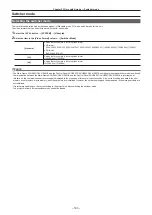
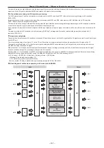
Input/output function in the 3G mode
r
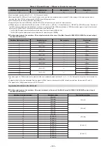
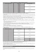
Relationship between the notation of the input terminals at the rear of the Main Frame AV‑HS60U1/AV‑HS60U2 and each input
function (for 3G mode)
Notation of the terminal at rear
Notation in menu
Color corrector
Frame delay
1
[SDI IN1]
―
―
3
[SDI IN2]
―
―
5
[SDI IN3]
―
―
7
[SDI IN4]
―
―
9
[SDI IN5]
―
―
11
[SDI IN6]
―
―
13
[SDI IN7]
―
―
15
[SDI IN8]
―
―
17
[SDI IN9]
―
―
19
[SDI IN10]
―
―
21
[SDI IN11]
―
―
23
[SDI IN12]
―
―
25
[SDI IN13]
l
―
27
[SDI IN14]
l
l
29
[SDI IN15]
l
―
Summary of Contents for AV-HS60C1E
Page 5: ...Please read this chapter and check the accessories before use Chapter 1 Overview ...
Page 52: ...This chapter describes menu operations Chapter 5 Basic Operations ...
Page 162: ...This chapter describes the difference with the Standard mode Chapter 9 3G mode 4K mode ...
Page 168: ...This chapter describes the terminals and signals of the unit Chapter 10 External Interfaces ...
Page 184: ...This chapter describes the setting menu table and terms Chapter 12 Appendix ...
Page 206: ...Web Site http www panasonic com Panasonic Corporation 2014 ...

