background image

18

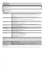
Specifications

Specifications

Power supply

AC   100 V to 240 V, 50 Hz/60 Hz

Power consumption

40 W

Supports redundant power supply.

 indicates safety information.

Control terminal

<MAIN FRAME> terminal

Compatible with 100Base-TX and AUTO-MDIX (For Main Frame AV-HS60U1/AV-HS60U2 connection)


f

Connection cable (supplied with AV-HS60C4): LAN cable (CAT5E), straight cable, STP (Shielded Twisted Pair), 10 m 

(32.8 ft)


f

Connector: RJ-45

When connected to the <LAN> terminal, no video will be displayed on the Menu Panel AV-HS60C3.

<MENU PANEL> terminal

Used only for the Menu Panel AV-HS60C3


f

Connector: DVI-D


f

Cannot be displayed on a DVI-D monitor because an independent signal format is used.


f

Cannot be used concurrently with a DVI-D monitor (computer) connected to the <DVI-D> terminal. Select with the 

display selector switch.

<DVI-D> terminal

Used for displaying menus to the DVI monitor (computer)


f

Connector: DVI-D


f

Monitor resolution: 1366

×

768 compatible monitor


f

Cannot be used concurrently with the <MENU PANEL> terminal. Select with the display selector switch.

<USB> terminal

For DVI monitor (computer) menu operation


f

Connector: USB (Type A, female)


f

Cannot be used for the Menu Panel AV-HS60C3.

Display selector switch

Switch for selecting <MENU PANEL> terminal or <DVI-D> terminal

<COM1 (M)> terminal

RS-422 control terminal

For master connection for controlling external devices


f

Connector: D-sub 9-pin (female), inch screw

<COM2 (RS-232)> terminal

RS-232 control terminal

For external device control connections


f

Connector: D-sub 9-pin (male), inch screw

<GPI I/O> terminal

GPI IN: 8 inputs, general-purpose, photocoupler sensing

ALARM OUT: 1 output, open collector output (negative logic)

GPI OUT: 10 outputs, selected from general purpose, tally

Open collector output


f

Connector: D-sub 25-pin (female), inch screw


f

Logic is switchable by menu.

ME number

2ME

Other

Ambient operating temperature

0 °C to 40 °C (32 °F to 104 °F)

Humidity

10% to 90% (no condensation)

Dimensions (W

×

H

×

D)

656 mm

×

160 mm

×

400 mm (25-27/32 inches

×

6-5/16 inches

×

15-3/4 inches) (excluding protrusions)

Mass

Approx. 15.0 k

]

 (33.1 lbs.) (excluding accessories)


r

For AV-HS60C4

Inrush current, measured according to European standard EN55103-1, on initial switch-on: 3 A, after a supply interruption of 5 s: 25 A (Each mains 
input)

Summary of Contents for AV-HS60C4E

Page 1: ...xcerpted version of the Operating Guide For more information please visit the Panasonic website http pro av panasonic net en manual index html and refer to the Operating Guide PDF Before operating this product please read the instructions carefully and save this manual for future use Please carefully read the Read this first P 2 to 6 of this Manual before use ...

Page 2: ...t please consult a qualified electrician WARNING To reduce the risk of fire or electric shock do not expose this equipment to rain or moisture To reduce the risk of fire or electric shock keep this equipment away from all liquids Use and store only in locations which are not exposed to the risk of dripping or splashing liquids and do not place any liquid containers on top of the equipment WARNING ...

Page 3: ...it NOTIFICATION Canada CAN ICES 3 A NMB 3 A IMPORTANT SAFETY INSTRUCTIONS 1 Read these instructions 2 Keep these instructions 3 Heed all warnings 4 Follow all instructions 5 Do not use this apparatus near water 6 Clean only with dry cloth 7 Do not block any ventilation openings Install in accordance with the manufacturer s instructions 8 Do not install near any heat sources such as radiators heat ...

Page 4: ...iners on top of the equipment WARNING Always keep switch blank caps large small and memory cards optional accessories out of the reach of babies and small children WARNING Fuse replacement should only be performed by qualified personnel For continued protection against risk of fire replace only with the same type 3 15 AH 250 V fuse for F1 F2 CAUTION Do not remove panel covers by unscrewing To redu...

Page 5: ...gital audio signals use cables designed for AES EBU Use shielded cables which provide quality performance for high frequency transmission applications for analog audio signals Other connecting cables IEEE1394 USB Use double shielded cables which provide quality performance for high frequency applications as connecting cables When connecting to the DVI signal terminal use a cable with a ferrite cor...

Page 6: ...be purchased from your local Panasonic Dealer How to replace the fuse 1 Open the fuse compartment with a screwdriver 2 Replace the fuse Fuse Manufactured by Panasonic Corporation Osaka Japan Importer s name and address of pursuant to EU rules Panasonic Marketing Europe GmbH Panasonic Testing Centre Winsbergring 15 22525 Hamburg Germany Декларація про Відповідність Вимогам Технічного Регламенту Обм...

Page 7: ... 18 How to read this document r r Abbreviations The following abbreviations are used in this document f f The model numbers of the Main Frames AV HS60U1P AV HS60U2P AV HS60U1E AV HS60U2E are described as AV HS60U1 AV HS60U2 f f The model numbers of the Control Panels AV HS60C1P AV HS60C2P AV HS60C1E AV HS60C2E are described as AV HS60C1 AV HS60C2 f f The model numbers of the Control Panels AV HS60...

Page 8: ...model number and electrical ratings of the unit are indicated on its rear panel Installation Refer to the Operating Guide of the AV HS6000 series Accessories f f AC cable AV HS60C4P 2 cables AV HS60C4E 4 cables f f LAN cable 1 cable used to connect with the Main Frame AV HS60U1 AV HS60U2 f f Switch blank cap large 16 caps f f Switch blank cap small 8 caps NOTE t t After removing the product from i...

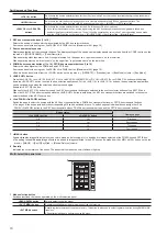
Page 9: ...IN8 SDI IN11 SDI IN12 Still 1V Still 2V Still 3V SDI IN10 8 SDI IN7 7 SDI IN6 6 SDI IN5 5 SDI IN4 1 2 3 4 5 6 7 8 1 1 KEY bus selector buttons KEY BUS DELEGATION Switches functions that can be operated using the KEY bus crosspoint buttons AUX 1 2 to AUX 15 16 buttons Switches to the source selector buttons for the AUX buses f f If you press the same buttons again while the AUX 1 2 to AUX 15 16 but...

Page 10: ...le holding down the BUS SHFT button to switch the bus selection applications For the AUX 1 2 to AUX 15 16 buttons the bus selection applications can be switched even when the selected button is pressed again Example KEY1 F S button When only the KEY1 F S button is pressed the KEY bus crosspoint buttons are switched to the source selector buttons of the KEY1 fill bus When the KEY1 F S button is pre...

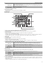
Page 11: ...he top menu BKGD Position tab Pattern Limit column 5 Transition type selection buttons NAM MIX WIPE EMEM LINK MIX button Switches images while overlapping During the transition the output total of the A bus and B bus is kept at 100 In background transition the above operation is applied when the NAM button is off If the NAM button is on images are switched between the A bus and the B bus with non ...

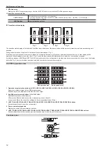
Page 12: ...ple operations of BKGD and KEY1 to KEY4 are performed in the next transition both sides may become unmatched In such a case the display will be like Fig 4 so move the fader lever back and forth to make the lever position recognize KEY DSK operation areas CG5V CG6V CAM1 CAM2 CG1V CG2V CG3V CG4V 1 2 3 4 5 1 2 3 4 5 KEY operation area DSK operation area 1 Operation target selection buttons KEY1 KEY2 ...

Page 13: ...completed r r Memory cards Memory cards used with the unit should conform to SD or SDHC standards Be sure to format memory cards using the unit Memory cards with the following capacity can be used for the unit The unit does not support SDXC memory cards SD memory card 8 MB to 2 GB SDHC memory card 4 GB to 32 GB For the latest information not available in the Operating Guide visit the following web...

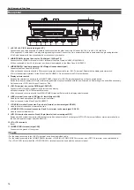
Page 14: ...ll not be performed properly if switched with the power turned on Restarting of the unit will be necessary Set the power to OFF and then set it back to ON 5 DVI D terminal connector DVI D signal DVI OUT Connects the DVI monitor computer used for the menu display f f Monitor resolution 1366 768 compatible monitor f f Cannot be used concurrently with the MENU PANEL terminal Select with the display s...

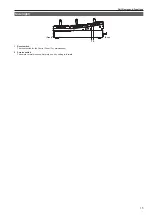
Page 15: ...rt Names and Functions 15 Side right 1 2 Front Rear 1 Reset switch The reset switch for the Control Panel For maintenance 2 Service switch The switch for maintenance Normally use it by setting to forward ...

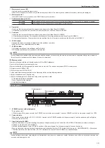
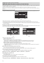
Page 16: ...4 4 4 6 4 5 4 7 4 9 4 8 OP STILL1 BUS SHFT 4 SDI IN3 3 SDI IN2 2 SDI IN1 1 Black 12 11 10 SDI IN9 9 SDI IN8 SDI IN11 SDI IN10 8 SDI IN7 7 SDI IN6 6 SDI IN5 5 SDI IN4 Red Red Blue Fig 2 Fig 3 1 Press the button blinking in red Fig 1 Update of the firmware is started f f Status when the firmware of the Control Panel is being updated Fig 2 Eight buttons out of the PGM A bus crosspoint buttons in the ...

Page 17: ...rmation in the following website and perform the software version update if necessary http pro av panasonic net English only f f The Control Panel AV HS60C4 operates normally only when the version of the software is 3 10 00 0 00 or later Be sure to perform the version update if the version of the software checked in step 1 is earlier than 3 10 00 0 00 ...

Page 18: ...th the display selector switch USB terminal For DVI monitor computer menu operation f f Connector USB Type A female f f Cannot be used for the Menu Panel AV HS60C3 Display selector switch Switch for selecting MENU PANEL terminal or DVI D terminal COM1 M terminal RS 422 control terminal For master connection for controlling external devices f f Connector D sub 9 pin female inch screw COM2 RS 232 te...

Page 19: ... 19 Memo ...

Page 20: ... proper treatment recovery and recycling of old products please take them to applicable collection points in accordance with your national legislation By disposing of them correctly you will help to save valuable resources and prevent any potential negative effects on human health and the environment For more information about collection and recycling please contact your local municipality dealer ...

Reviews: