Part Names and Functions
9
Part Names and Functions
Operation panel
CHR
LIN
LUM
FULL
4
SDI
IN3
3
SDI
IN2
2
SDI
IN1
1
Black
16
15
14
13
12
11
10
SDI
IN9
9
SDI
IN8
SDI
IN11
SDI
IN12
Still
1V
Still
2V
Still
3V
SDI
IN10
8
SDI
IN7
7
SDI
IN6
6
SDI
IN5
5
SDI
IN4
RECALL
STORE
DEL
RECALL
CBGD
STORE
DEL
MIX
02s01f
MIX
01s00f
MIX
01s00f
WIPE
01s00f
CHR
LIN
FULL
FULL
WIPE
01s00f
MIX
01s00f
MIX
01s00f
MIX
CG5V
CG6V
CAM1
CAM2
CG5V
CG6V
CAM1
CAM2
CG1V
CG2V
CG3V
CG4V
01s00f
MIX
ME2
01s00f
MIX
ME1
01s00f
BUS
SHFT
BUS
SHFT
1-7
4-1
1-8
1-9
SHOT000
1-1
SHOT001
1-2
SHOT002
1-3
SHOT003
1-4
1-5
1-6
PLAY
SEL
AUK
DSK
ME2
XPT
ME1
4
SDI
IN3
3
SDI
IN2
2
SDI
IN1
1
Black
16
15
14
13
12
11
10
SDI
IN9
9
SDI
IN8
SDI
IN11
SDI
IN12
Still
1V
Still
2V
Still
3V
SDI
IN10
8
SDI
IN7
7
SDI
IN6
6
SDI
IN5
5
SDI
IN4
4-3
4-2
4-4
4-6
4-5
4-7
4-9
4-8
OP
STILL1
1
2
3
4
5
1
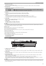
Crosspoint area
2
Multi-selection panel area
3
Transition area
4 KEY/DSK operation area
5
Positioner area
Crosspoint area
4
SDI
IN3
3
SDI
IN2
2
SDI
IN1
1
Black
16
15
14
13
12
11
10
SDI
IN9
9
SDI
IN8
SDI
IN11
SDI
IN12
Still
1V
Still
2V
Still
3V
SDI
IN10
8
SDI
IN7
7
SDI
IN6
6
SDI
IN5
5
SDI
IN4
BUS
SHFT
BUS
SHFT
4
SDI
IN3
3
SDI
IN2
2
SDI
IN1
1
Black
16
15
14
13
12
11
10
SDI
IN9
9
SDI
IN8
SDI
IN11
SDI
IN12
Still
1V
Still
2V
Still
3V
SDI
IN10
8
SDI
IN7
7
SDI
IN6
6
SDI
IN5
5
SDI
IN4
1
2
3
4
5
6
7
8
1
1
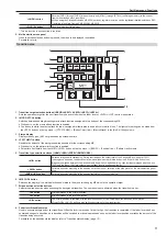
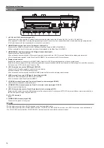
KEY bus selector buttons (KEY BUS DELEGATION)
Switches functions that can be operated using the KEY bus crosspoint buttons.
<AUX 1/2> to <AUX 15/16>
buttons
Switches to the source selector buttons for the AUX buses.
f
If you press the same buttons again while the <AUX 1/2> to <AUX 15/16> buttons are selected, the bus in the
background is selected.
Example)
If you press the <AUX 1/2> button again while the AUX1 bus is selected, the AUX2 bus is selected.
f
The <AUX 1/2> to <AUX 3/4> buttons have the MIX transition function.
f
The <AUX 1/2> to <AUX 15/16> buttons have the crosspoint link coupling function.
<KEY1 F/S> to <KEY4 F/S>
buttons
Switches to the source selector buttons for the key fill buses or key source buses.
f
If you select key fill signal or key source signal using the KEY bus crosspoint buttons, the signals are linked and
another signal is automatically selected. The unit’s linking operation has two modes. The mode setting can be made
from the <CONF> button on the top menu
→
[SOURCE LINK]
→
[Key Assign] tab
→
[Master/Slave].
<VMEM F/S> button
Switches the source selector buttons for the fill buses or source buses of [CLIP1] through [CLIP4] (video memory) and
[STILL1] through [STILL4] (still image memory) input buses.
<DISP> button
Switches to the source selector buttons for the DISP buses to be displayed on the Menu Panel AV-HS60C3.
Summary of Contents for AV-HS60C4E
Page 19: ... 19 Memo ...


