
Summary of Contents for AW-PB306
Page 11: ......
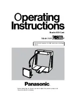
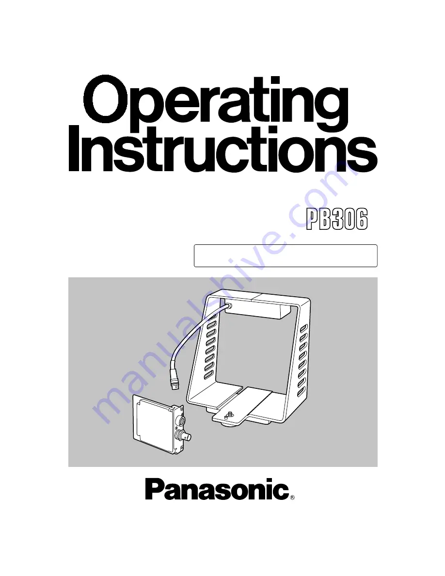
The Panasonic AW-PB306 Operating Instructions Manual is an essential resource for maximizing the potential of your device. Easily download this detailed manual for free from our website, providing you with all the necessary instructions to navigate and optimize your Panasonic AW-PB306.
Page 11: ......


