background image

PANASONIC BROADCAST & TELEVISION SYSTEMS COMPANY
DIVISION OF MATSUSHITA ELECTRIC CORPORATION OF AMERICA

Executive Office:
3330 Cahuenga Blvd W., Los Angeles, CA 90068   (323) 436-3500

EASTERN ZONE: 
One Panasonic Way 4E-7, Secaucus, NJ 07094   (201) 348-7621

Southeast Region:
1225 Northbrook Parkway, Ste 1-160, Suwanee, GA 30024   (770) 338-6835
Central Region:
1707 N Randall Road E1-C-1, Elgin, IL 60123   (847) 468-5200

WESTERN ZONE: 
3330 Cahuenga Blvd W., Los Angeles, CA 90068   (323) 436-3500

Government Marketing Department:
52 West Gude Drive, Rockville, MD 20850   (301) 738-3840

Broadcast PARTS INFORMATION & ORDERING:
9:00 a.m. – 5:00 p.m. (EST) (800) 334-4881/24 Hr. Fax (800) 334-4880
Emergency after hour parts orders (800) 334-4881

TECHNICAL SUPPORT:
Emergency 24 Hour Service (800) 222-0741

Panasonic Canada Inc.
5770 Ambler Drive, Mississauga, Ontario L4W 2T3   (905) 624-5010

Panasonic de Mexico S.A. de C.V.
Av angel Urraza Num. 1209 Col. de Valle 03100 Mexico, D.F. (52) 1 951 2127

Panasonic Sales Company
Division of Matsushita Electric of Puerto Rico Inc.
San Gabriel Industrial Park, 65th Infantry Ave., Km. 9.5, Carolina, Puerto Rico 00630   (787) 750-4300

F0701W1071 

@

Printed in Japan
VQT9295

P

Summary of Contents for AW-PB306

Page 1: ...Model AW P Before attempting to connect operate or adjust this product please read these instructions completely Studio SDI Card This product consists of an SDI card and an interface bracket ...

Page 2: ...RIC SHOCK DO NOT REMOVE COVER OR BACK NO USER SERVICEABLE PARTS INSIDE REFER TO SERVICING TO QUALIFIED SERVICE PERSONNEL The lightning flash with arrowhead symbol within an equilateral triangle is intended to alert the user to the presence of uninsulated dangerous voltage within the product s enclosure that may be of sufficient magnitude to constitute a risk of electric shock to persons The exclam...

Page 3: ...ard and an interface bracket The EVF I F cable of the interface bracket must be connected to the connector on the SDI card before use If this connection is not performed signals will not be output from the SDI card OWhen connecting or disconnecting a cable from any unit ensure that the power to that unit is turned off ODo not drop this product or subject it to strong shock or vibration as this may...

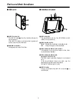
Page 4: ...T BY Places the viewfinder in standby mode ON Outputs images to the viewfinder 5Inter communications level control This adjusts the sound level output to the inter communications headset 6Inter communications jack plug type 1 8 3 5 mm The inter communications headset is connected here If the plug diameter does not match use the adjuster plug supplied with this product 1 4 5 1 8 6 35 mm 5 3 5 mm 7E...

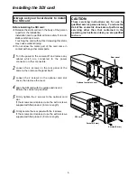
Page 5: ...n the 4 screws on the rear panel of the camera then remove the panel itself 3Loosen the 2 screws on the optional card slot cover then remove the cover 4Align the SDI card with the guides and insert it Ensure the card is fully inserted 5Firmly tighten the 2 screws to the optional card slot If the screws are misplaced use the extra screws supplied with this product 6 mm in length 6Firmly secure the ...

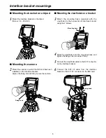
Page 6: ...ach the mounting base supplied with the viewfinder to the top section of interface bracket using the 2 screws 4Slide the viewfinder onto the mounting base and tighten the fixing knob to secure it firmly 5Connect the viewfinder cable to the EVF connector on the interface bracket 1Mount the interface bracket on the tripod Screw 1 4 20 UNC Mounting the camera Mounting the viewfinder on a bracket Moun...

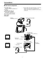
Page 7: ...ons headset Video monitor SDI monitor OUse the RCU cable AW CA50A26 to connect the remote control unit to the convertible camera Power to the camera is supplied from the remote control unit Inter communications headset Inter communications headset Convertible camera AW E300 AW E600 AW E800A etc Viewfinder WV VF65B AW VF80 etc Remote control unit RCU WV RC700A WV RC550 etc RCU cable AW CA50A26 Coax...

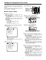
Page 8: ...tings 1Display the main menu When performing the settings with the convertible camera Press the MENU button continuously for at least 5 seconds When performing the settings with the remote control unit OWV RC700A Set the USER SET switch to ON OWV RC550 Set the SET UP switch to 1 or 2 2Select Option Card Set to display the submenu When performing the settings with the convertible camera Press the M...

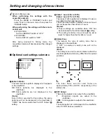
Page 9: ...r if CVBS has been selected as the EVF Output 4 setting 2Zebra 1 Level 70 to 109 Zebra 2 Level 71 to 110 Two types of zebra patterns are displayed to use as a yardstick for the brightness level The striped zebra pattern display of Zebra 2 Level is more dense than that of Zebra 1 Level Notes OThese settings are available when ON has been selected for the Zebra Indicator 1 setting OThe setting for Z...

Page 10: ...NC compliant with SMPTE259M standard EVF I F connector 12 pin round Interface bracket EVF connector 12 pin round composite signals brightness signals 1 0 V P P Inter communications jack plug type 1 8 3 5 mm Switch control functions Interface bracket EVF standby switch STANDBY ON Inter communications level control Menu screens Zebra Indicator ON OFF Zebra 1 Level 70 to 109 Zebra 2 Level 71 to 110 S...

Page 11: ......

Page 12: ...ernment Marketing Department 52 West Gude Drive Rockville MD 20850 301 738 3840 Broadcast PARTS INFORMATION ORDERING 9 00 a m 5 00 p m EST 800 334 4881 24 Hr Fax 800 334 4880 Emergency after hour parts orders 800 334 4881 TECHNICAL SUPPORT Emergency 24 Hour Service 800 222 0741 Panasonic Canada Inc 5770 Ambler Drive Mississauga Ontario L4W 2T3 905 624 5010 Panasonic de Mexico S A de C V Av angel U...

Reviews: