-17-
2) Adjust the cable compensation, genlock, and total
pedestal of the selected camera.
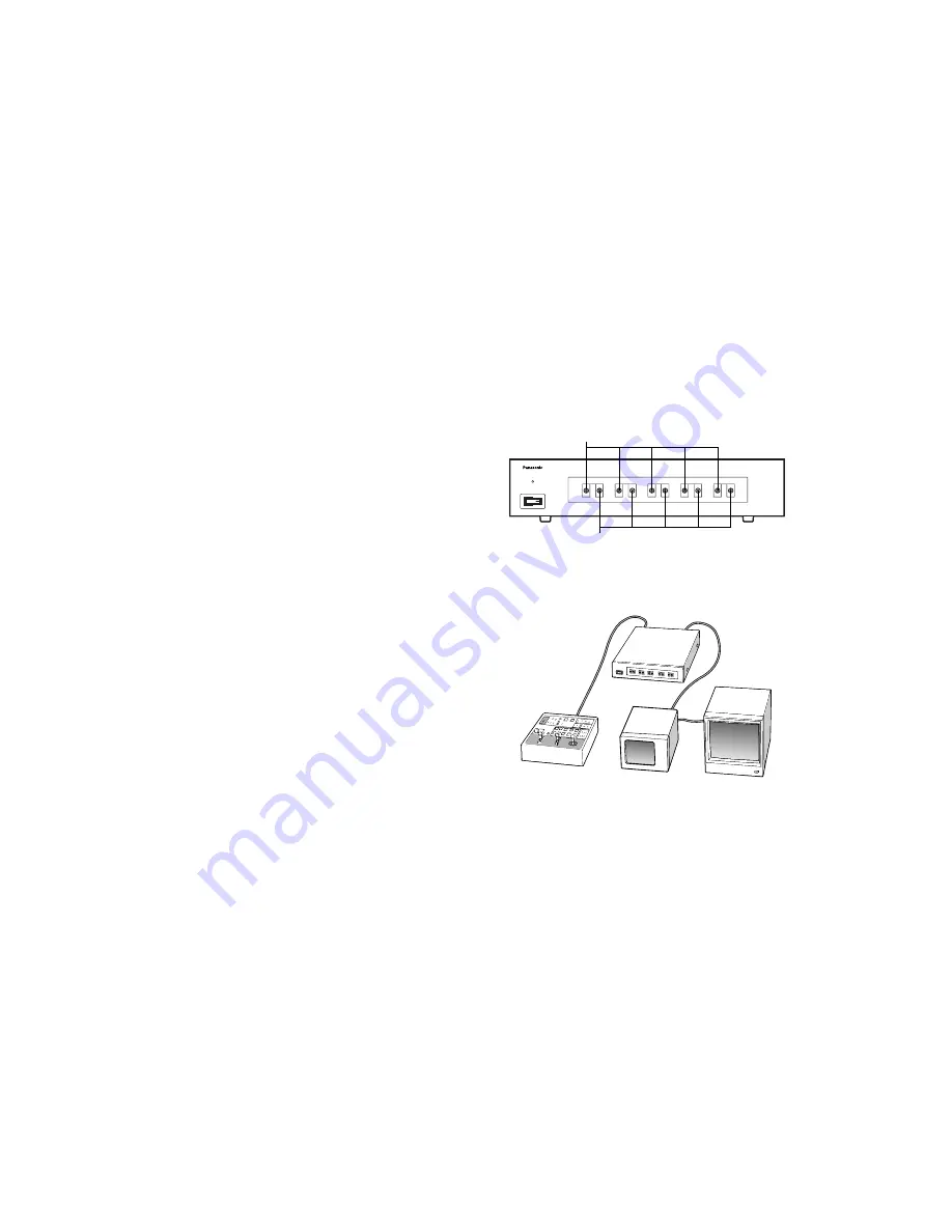
• Cable Compensation
Signal degradation due to cable length between the con-
trol panel and the pan/tilt head can be compensated for.
q
If the cable length from the pan/tilt head to the control
panel is longer than 300 meters, set the cable com-
pensation switch on the pan/tilt head to the ON posi-
tion. For details, refer to INSTALLATION OF PAN/TILT
HEAD at page 8 or the Operating Instructions for
Pan/tilt Head.
w
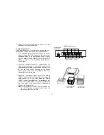
Connect a waveform monitor or a vectorscope to the
video output connector on the control panel for the
corresponding the camera pan/tilt head number ([1] to
[5]), set the video output connector on the control
panel, set the mode switch to the BAR position, then
observe the color bar signals.
e
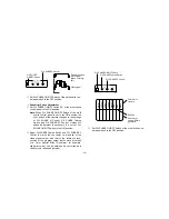
Adjust the Y (luminance) signal level with the CABLE
COMP Y control for the corresponding camera pan/tilt
head number ([1] to [5]), then adjust the CABLE
COMP Y control then adjust the C (chrominance) sig-
nal level with CABLE COMP C control. Repeat this until
the video output of the control panel is adjusted as
shown in the figure below.
Note:
Turning CABLE COMP Y control changes not
only the Y (luminance) signal level but also the
video signal levels as a whole.
P O W E R
1
Y
C
2
Y
C
3
Y
C
4
Y
C
5
Y
C
O F F
O N
C A B L E C O M P
M u l t l P o r t H u b A W - H 8 5 0 5
Waveform Monitor
Vector Scope
Color Monitor
(75
Ω
termination)
CABLE COMP C Control
CABLE COMP Y Control
Multiport Hub
AW-HB505


