background image

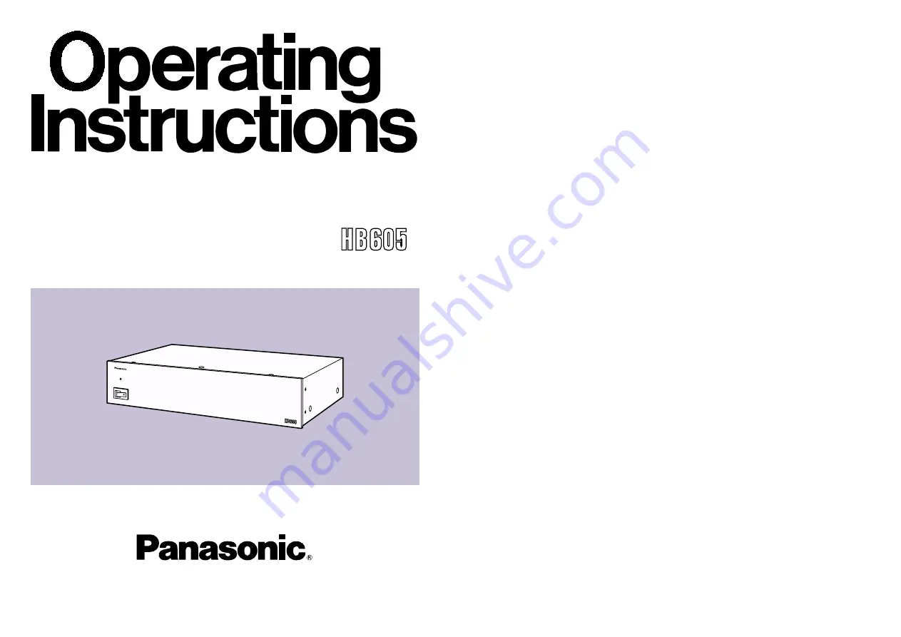
Before attempting to connect, operate or adjust this product, please
read these instructions completely.

POWER

OFF

ON

M u l t i   C o n t r o

l   H u b   A W –

Multi Control Hub

Model AW-

P

Summary of Contents for AWHB605 - MULTI CONTROL HUB

Page 1: ...Before attempting to connect operate or adjust this product please read these instructions completely POWER OFF ON M u l t i C o n t r o l H u b A W Multi Control Hub Model AW P ...

Page 2: ... limits for a class A digital device pursuant to Part 15 of the FCC Rules These limits are designed to provide reasonable protection against harmful interference when the equipment is operated in a commercial environment This equipment generates uses and can radiate radio frequency energy and if not installed and used in accordance with the instruction manual may cause harmful interference to radi...

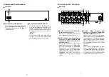
Page 3: ...horoughly Accessories O Priority switchboxes 5 O Rack mounting brackets 12 O Mounting screws 24 Overview O The AW HB605 multi control hub combines with a system such as the Panasonic AW PH300 series indoor pan tilt head or AW PH600 series outdoor pan tilt head to support the connection of between one and five control panels AW RP501 AW RP301 AW RP305 to a single camera and pan tilt head Any of the...

Page 4: ...ory 5 straight cable 5 Preview Video Signal Input Connector TO PAN TILT HEAD HUB PREVIEW IN BNC Connector Connect this connector to the video signal output connector VIDEO OUT of the pan tilt head or to the preview video signal output connector TO CONTROL PANEL PREVIEW OUT of the multi port hub using a coaxial cable 5C 2V equivalent Note In a system incorporating the AW RP301 or AW RP305 the contr...

Page 5: ...nput connector G L IN of the pan tilt head or to the G L signal input connector TO CONTROL PANEL G L IN of the multi port hub using a coaxial cable 5C 2V equivalent 7 Camera Control Output Connector TO PAN TILT HEAD HUB CAM CONT OUT BNC Connector Connect this connector to the camera control signal input connector CAMERA CONTROL IN of the pan tilt head or to the camera control signal input connecto...

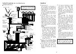
Page 6: ...15 camera cable O Connect the electric zoom lens iris control cable to the camera and the remote zoom and focus control cable to the pan tilt head Cord clamper Control panel AC adapter AW PS301 DC cord Remote zoom focus control cable Iris control cable To lens interface connector To iris connector Controls and Their Functions Priority Switchbox Contacts Terminal Panel These are the output contacts...

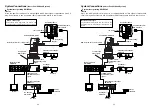
Page 7: ...gth The maximum cable length from the camera and pan tilt head to the multi pan tilt control panel is 500 meters O I PREVIEW OUT CAM CONT IN 5 PAN TILT CONTROL IN BLACK BURST OUT PREVIEW OUT CAM CONT IN 4 PAN TILT CONTROL IN BLACK BURST OUT PREVIEW OUT TO CONTROL PANEL TO PAN TILT HEAD HUB CAM CONT IN 3 PAN TILT CONTROL IN BLACK BURST OUT PREVIEW OUT CAM CONT IN 2 PAN TILT CONTROL IN BLACK BURST O...

Page 8: ...10BASE T cable Pan tilt head control signal System Incorporating AW RP505 or AW HB505 Maximum Cable Length The maximum cable length from the camera and pan tilt head to the multi hybrid control panel is 500 meters MENU OPT CN CARD VIDEO OUT LF REMCTE GL N DC12V IN IRIS TEM AWC YES ABC NO BAR PREVIEW OUT CAM CONT IN 5 PAN TILT CONTROL IN BLACK BURST OUT PREVIEW OUT CAM CONT IN 4 PAN TILT CONTROL IN...

Page 9: ...ches as appropriate For detailed instructions refer to the manuals accompanying the relevant equipment Note After performing G L gen lock adjustment and total pedestal adjustment set the control panel s G L phase adjustment switch to the OFF position The instruction manual of the hybrid control panel states that this switch should be left in the ON position but it should be set to OFF on systems u...

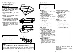
Page 10: ...6 kg Finish Cover Steel panel with AV ivory color polyvinyl chloride finish approximate color Munsell 7 9Y 6 8 0 8 Panel AV ivory color paint approximate color Munsell 7 9Y 6 8 0 8 Rack Mounting Example Rack Mounting Procedure Multi Control Hub To mount the multi control hub on a rack use the supplied rack mounting brackets and mounting screws M4a10 1 Press the power switch to turn power off 2 Rem...

Page 11: ...4 770 338 6835 Central Region 1707 N Randall Road E1 C 1 Elgin IL 60123 847 468 5200 WESTERN ZONE 3330 Cahuenga Blvd W Los Angeles CA 90068 323 436 3500 Dallas Region 6226 Abington Way Houston TX 77008 713 802 2726 No CA Northwest Region 5870 Stoneridge 3 Pleasanton CA 94588 925 416 5108 Government Marketing Department 52 West Gude Drive Rockville MD 20850 301 738 3840 Panasonic Canada Inc 5770 Am...

Reviews: