background image

SPECIFICATIONS

[AW-RP501]

Source Voltage :

12 V DC (DC jack)

Power Consumption :

12V, 0.7A

Video Input :

1.0 V[p-p] composite/75

(BNC connector)

Genlock Input :

black burst 
75 

loop through with auto terminator (BNC connector)

Video Output :

1.0 V[p-p] composite/75 

x 2 (BNC connector)

S-video Output :

Y: 0.7 V[p-p] (75 

)

C: 0.3 V[p-p] burst level chrominance/75 

(S-VIDEO connector)

Genlock Output :

75 

(BNC connector)

Camera Control Output :

Control signal (BNC connector)

Pan/tilt Control Output :

Control signal (RJ-45 8P modular jack)

System Tally Input :

Tally signal (2 pin Terminal block)

Auxiliary Control Input :

Control signal (8 pin DIN connector)
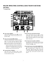
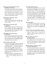
Switches :

Power ON/OFF Switch, GAIN HIGH/MID/LOW Switch, GAIN AGC/MANU Switch,
MODE BAR/CAM switch  SHUTTER Switch, AUTO/ATW ATW switch, AUTO/ATW A switch,
AUTO/ATW B switch, AWC Switch, ABC Switch, G/L PHASE ON/OFF Switch,
G/L PHASE Coarse Switch, IRIS AUTO/MANU Switch, MEMORY Switch, PRESET Switch,
DEF Switch, WIP Switch, H/F Switch, EXT Switch, ND Switch, OP Switch, SPEED Switch,
SPEED SW CHANGE Switch, ZOOM REVERSE Switch, ZOOM/FOCUS EXCHANGE Switch,
FOCUS REVERSE Switch, TILT REVERSE Switch, PAN REVERSE Switch

Controls :

T. PED Control, G/L PHASE SC Control, G/L PHASE H Control, CABLE COMP Y Control,
CABLE COMP C Control, IRIS LEVEL Control, ZOOM Lever, FOCUS Lever, PAN/TILT Lever

Pan/tilt Head Connecting
Cable :

x 4 (Coaxial Cable 3 pcs., 10BASE-T straight cable 1 pc.)(In case of using G/L function)

Maximum cable length :

500 m (In case of using coaxial cables 5C-2V and 10BASE-T cable UTP category-5)

Operating temperature :

10°C to +45°C (14°F to +113°F)

Dimensions :

210 (W) x 88 (H) x 177 (D) mm [8-1/4" (W) x 3-1/2" (H) x 7" (D)]

Weight :

2.2 

kg

(4.9 lbs.)

Finish :

AV Ivory painting

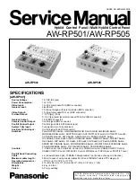
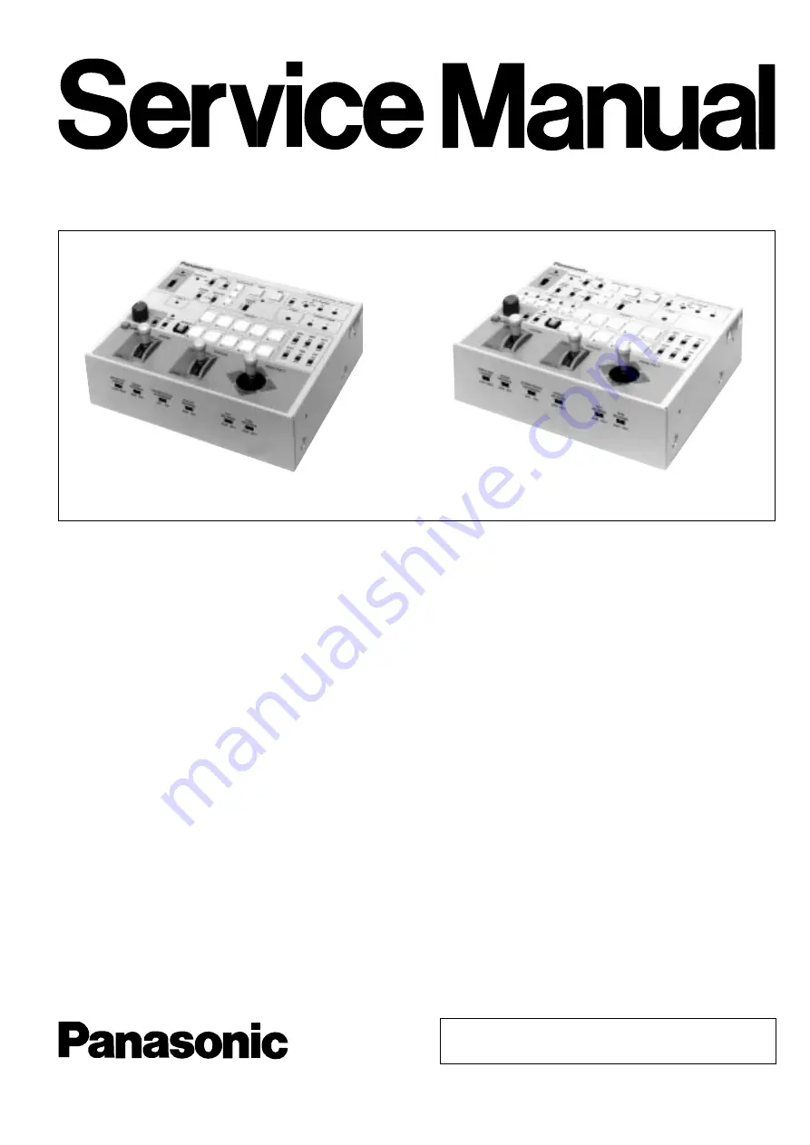
Hyblid  Control  Panel / Multi Hyblid Control Panel

AW-RP501/AW-RP505

ORDER NO. BSD9803029C8

C

1 9 9 8     M a t s u s h i t a   C o m m u n i c a t i o n   I n d u s t r i a l   C o . ,   L t d .

A l l   r i g h t s   r e s e r v e d .   U n a u t h o r i z e d   c o p y i n g   a n d
d i s t r i b u t i o n   i s   a   v i o l a t i o n   o f   l a w .

AW-RP501

AW-RP505

Summary of Contents for AWRP501 - HYBRID CONTROL PANEL

Page 1: ...U Switch MEMORY Switch PRESET Switch DEF Switch WIP Switch H F Switch EXT Switch ND Switch OP Switch SPEED Switch SPEED SW CHANGE Switch ZOOM REVERSE Switch ZOOM FOCUS EXCHANGE Switch FOCUS REVERSE Switch TILT REVERSE Switch PAN REVERSE Switch Controls T PED Control G L PHASE SC Control G L PHASE H Control CABLE COMP Y Control CABLE COMP C Control IRIS LEVEL Control ZOOM Lever FOCUS Lever PAN TILT...

Page 2: ...permission of manufacture IMPORTANT SAFETY NOTICE AW RP505 Source Voltage 12 V DC DC jack Power Consumption 12 V 0 5 A Preview Video Input 1 0 V p p composite 75Ω BNC connector Genlock Input black burst 75Ω loop through with auto terminator BNC connector Preview Video Output 1 0 V p p composite 75Ω BNC connector Genlock Output 75Ω BNC connector Camera Control Output Control signal BNC connector Pa...

Page 3: ...N for AW RP501 17 Main Board 2 2 PT MICOM SECTION 18 SW CAM Board 19 Schematic Diagram SW CAM Board 21 Main Board 1 2 CABLE Y C SECTION for AW RP501 22 Main Board 2 2 PT MICOM SECTION 22 Rear Board 24 Conductor View SW CAM Board 20 Main Board 23 Rear Board 25 Joystick Board 25 Exploded View 26 Replacement Parts List 27 ...

Page 4: ...switch is set to the OFF position the camera is totally switched off but the communication line between the pan tilt head and this control panel remains live To disconnect all power supply pull out the power plug from the electrical outlet e Operating Indicator OPERATE Lights green when communication begins normally between the camera and the control panel and goes out if a communication error occ...

Page 5: ...lance may not be adjustable if there is no white in the image being taken by the camera For details refer to the Operating Instructions for the Camera 2 Auto Black Start Switch ABC When this switch is depressed the lens iris is automati cally closed to set black balance Be sure to keep the IRIS AUTO MANU Switch 5 in the AUTO position in setting black balance Auto Set Indicator 3 flashes while ABC ...

Page 6: ...es not only the Y luminance signal level but also the whole video signal level 1 Cable Compensation Chrominance Control CABLE COMP C Used to adjust the C chrominance signal level of video output signals as appropriate to the cable length between the pan tilt head and this control panel To adjust it first set MODE BAR CAM Switch r to the BAR position then connect a waveform monitor vec torscope or ...

Page 7: ...anually controlled over the range from the closed posi tion to the fully open position using IRIS LEVEL Control 6 Set the switch to the MANU position in storing iris data in PRESET Switches 8 with MEMORY Switch 7 If the switch is in the AUTO position iris data will not be stored in the memory 6 Lens Iris Control IRIS LEVEL When IRIS AUTO MANU Switch 5 is in the MANU position the iris can be contro...

Page 8: ... tilt head moves in the opposite direction if the TILT REVERSE Switch 4 is in the REV position The pan tilt head turns leftward when the lever is moved toward LEFT or rightward when it is moved toward RIGHT provided that PAN REVERSE Switch 5 is in the NOR position The pan tilt head moves in the opposite direc tion if the PAN REVERSE Switch 5 is in the REV posi tion Note TILT REVERSE Switch 4 and P...

Page 9: ...Connect it to the G L input connector G L IN on the pan tilt head with a coaxial cable 5C 2V or equivalent in operating the camera in external sync mode The cable can be extended up to 500 meters 5 Camera Control Output Connector TO CAMERA PAN TILT HEAD CAMERA CONTROL OUT BNC Connector Connect it to camera control input connector CAMERA CONTROL IN on the pan tilt head with a coaxial cable 5C 2V or...

Page 10: ...ch ZOOM FOCUS EXCHANGE ON OFF ZOOM Lever 6 and FOCUS Lever 7 exchange their function between them when this switch is set to the ON position Unless this exchange is needed keep the switch in the OFF position 0 1 2 3 4 5 With ZOOM FOCUS EXCHANGE Switch 2 in the ON position the operations shown on the panel do not agree with the indications on the panel In this case paste the supplied seal on the pa...

Page 11: ...tion AW RP505 Control Panel Note TILT REVERSE Switch 4 and PAN REVERSE Switch 5 may be used to reverse the operating direction of the pan tilt head but be sure to set the operating direction of the pan tilt head with its mounting direction selection switch during its instal lation depending on whether the pan tilt head is mounted on the floor or is suspended Unless the mounting direction selection...

Page 12: ...l is not high enough even if the iris is wide open set the switch to the MID or HIGH position After selecting it set CAM CONT Switch r back to the OFF position i Electronic Shutter Speed Selection Switch SHUTTER ELC 1 100 OFF Used to select a mode of camera electronic shutter con trol Select a camera with CONTROL Switch 2 set CAM CONT Switch r to the ON position then select ELC 1 100 or OFF With t...

Page 13: ...2 when both CAM CONT Switch r and G L PHASE Switch 6 are in the ON position the genlock phase settings of the newly selected camera will be similarly changed Before changing the camera for another set G L PHASE Switch 6 back to the OFF position 7 Genlock Subcarrier Phase Coarse Switch G L PHASE 0 90 180 270 Used for coarse adjustment of the colour phases of gen lock input and video output signals ...

Page 14: ... at the same time press one of the 10 buttons of PRESET Switch 8 as desired The pressed button in which the selected item is stored lights 2 Camera Pan tilt Head Selection Switch CONTROL Select a desired camera with pan tilt head from among those connected to the control panel When a camera with pan tilt head is selected by pressing one of the but tons 1 to 5 the pressed button lights Note Even if...

Page 15: ...lever The pan tilt head turns up when the lever is moved toward UP or down when it is moved toward DOWN provided that TILT REVERSE Switch 3 is in the NOR position 9 Speed Selection Switch SPEED If ZOOM lever 6 FOCUS Lever 7 or PAN TILT Lever 8 is moved while keeping SPEED Switch 9 depressed the corresponding operation takes place at low speed provided that SPEED SW CHANGE Switch 9 is in the LOW po...

Page 16: ...irection if the TILT REVERSE Switch 3 is in the REV position The pan tilt head turns leftward when the lever is moved toward LEFT or rightward when it is moved toward RIGHT provided that PAN REVERSE Switch 4 is in the NOR position The pan tilt head moves in the oppo site direction if the PAN REVERSE Switch 4 is in the REV position Note TILT REVERSE Switch 3 and PAN REVERSE Switch 4 may be used to ...

Page 17: ...oaxial cable Note The preview video signals are for confirmation of which camera has been selected so the picture quality proper to the camera cannot be guaranteed To output camera video signals use video output connector VIDEO OUT or S video output connec tor S VIDEO OUT on the Multiport Hub 8 Genlock Input Connectors G L IN BNC Connector Black burst signals or are input to one of the two con nec...

Page 18: ...S Lever 7 or PAN TILT Lever 8 is moved while keeping SPEED Switch 9 depressed the corresponding operation takes place at low speed pro vided that SPEED SW CHANGE Switch 9 is in the LOW position If one of these levers is moved with SPEED Switch 9 depressed when SPEED SW CHANGE Switch 9 is in the HIGH position the corre sponding operation takes place at high speed The speed polarity can also be chan...

Page 19: ...LECT5 SELECT LED1 SELECT LED2 SELECT LED3 SELECT LED4 SELECT LED5 AWC CONT1 AWC CONT2 NC SPARE 1 2 3 4 5 6 7 8 9 10 11 12 13 P107 5V OUT 5V OUT 9V OUT GND GND GND IRIS OUT A M OUT LAMP LAMP LED POWER CONT 1 2 3 4 5 6 7 8 9 10 11 P104 LED1 LED2 LED3 LED4 LED5 LED6 LED7 LED8 LED9 LED10 ALARM ATW LED A LED B LED 1 2 3 4 5 6 7 8 9 10 11 12 13 14 P105 P SET1 P SET2 P SET3 P SET4 P SET5 P SET6 P SET7 P ...

Page 20: ...MP U3 b AMP U3 a 5 4 8 1 BUFFER Q21 Q24 BUFFER Q30 Q33 69 RATI SYNC SEPA U7 5 2 CLAMP Q25 Q26 U8 AMP U10 3 12 BUFFER Q34 BUFFER Q27 Q29 BUFFER AMP U12 3 12 BUFFER Q39 Q42 Q35 Q38 BIAS U11 AMP U9 1 4 BUFFER Q43 Q45 70 NTPL 74 DTR 76 PMN 79 8PF 68 APCN VP5 10 10 AMP U13 b 8 5 AMP U13 a 1 4 BLOCK DIAGRAM OF MAIN BOARD 1 2 Cable Y C SECTION 1 2 3 4 5 6 7 8 9 10 11 12 13 14 VIDEO IN GND G L OUT 1 GND V...

Page 21: ...10 P11 P12 RXD TXD RESET EIORD EIOWR CLK P00 P01 P02 P03 P04 OE CE A0 A12 7 8 69 68 22 20 32 33 35 36 38 43 45 47 49 50 2 10 21 23 27 2 10 21 23 25 A0 A12 CS2 WE OE CS1 26 27 22 20 A13 51 54 58 60 62 D0 D7 D0 D7 D0 D7 I1 I2 I3 I4 I5 O1 O2 O3 O4 O5 U509 BUFFER I1 I2 I3 I4 I5 O1 O2 O3 O4 O5 88 87 86 85 83 75 74 73 72 71 79 78 76 29 30 59 9 10 24 1 2 3 4 5 18 17 16 15 14 18 17 16 15 14 1 2 3 4 5 A0 A...

Page 22: ...R X0 X1 X2 X3 X4 X5 X6 X7 X 3 13 14 15 12 1 5 2 4 1V 4V A B C 11 10 9 SEL0 SEL1 SEL2 U8 SELECTOR X0 X1 X2 X3 X4 X5 X6 X7 X 3 13 14 15 12 1 5 2 4 A B C 11 10 9 SEL0 SEL1 SEL2 A M IRIS IRIS 1 2 3 4 HIGH MID LOW BUFFER U9 a BUFFER U10 a BUFFER U9 d BUFFER U9 b U17 a COMPARATOR BUFFER U10 b 1V 4V 1V 5V ADC0 ADC1 ADC2 3 2 1 U20 MICROPROCESSOR P44 P45 P46 44 43 42 SEL0 SEL1 SEL2 25 OSC1 OSC2 26 Y1 5V 24...

Page 23: ...6 9 9 XTN3 6BFN XSB3 6FX XSB3 12FN XSB2 4FXK XTB3 6BFX XSB3 6FN XSB4 8FN XSB5 8FN XXE26D4FXK XTS3 8BFX 1 2 3 4 5 6 7 8 9 10 Pan Head Tapping Screws Binding Head Screws Binding Head Screws Binding Head Black Screws Binding Head Tapping Screws Binding Head Screws Binding Head Screws Binding Head Screws Hex Slotted Head Black Screws Flush Head Tapping Screws Screws No Description Numbers show screws ...

Page 24: ...4 Screw Caution Label PCB1 RTL YWWRP51JKZ2A Printed Circuit Board Assy for AW RP501 USA Canada YWWRP51EKZ2A Printed Circuit Board Assy for AW RP501 B G U1 YWCXD2044Q IC U2 YWUPC1862GS IC U3 NJM2268M IC U4 6 YWTC7S04FL IC U7 YWLM1881M IC U8 YWTC7S08FL IC U9 YWNJM2267M IC U10 NJM1496M IC U11 TL092CPS IC U12 NJM1496M IC U13 YWNJM2267M IC U501 502 MC74HC240AF IC U504 YWHM6264BLFP IC U505 KL5C8012CFP I...

Page 25: ...R00 Carbon 0 ohm 1 16W R26 ERJ3GEYJ103 Carbon 10K ohms 1 16W for AW RP501 B G R27 ERJ3GEY0R00 Carbon 0 ohm 1 16W for AW RP501 USA Canada R28 ERJ3GEYJ103 Carbon 10K ohms 1 16W R31 33 ERJ3GEY0R00 Carbon 0 ohm 1 16W R35 ERJ3GEYJ103 Carbon 10K ohms 1 16W R36 ERJ3RHD332 Metal 3 3K ohms 1 16W R37 ERJ3GEYJ102 Carbon 1K ohms 1 16W R38 39 ERJ3RHD102 Metal 1K ohms 1 16W R42 ERJ3RHD332 Metal 3 3K ohms 1 16W ...

Page 26: ...rbon 620 ohms 1 16W R130 ERJ3GEYJ684 Carbon 680K ohms 1 16W R131 ERJ3GEYJ562 Carbon 5 6K ohms 1 16W R132 ERJ3GEY0R00 Carbon 0 ohm 1 16W R133 ERJ3GEYJ273 Carbon 27K ohms 1 16W R134 ERJ3RHD243 Metal 24K ohms 1 16W R135 ERJ3RHD163 Metal 16K ohms 1 16W R136 ERJ3GEYJ103 Carbon 10K ohms 1 16W R137 ERJ3GEYJ332 Carbon 3 3K ohms 1 16W R138 ERJ3GEYJ681 Carbon 680 ohms 1 16W R139 ERJ3GEYJ222 Carbon 2 2K ohms...

Page 27: ... ohms 1 16W R533 ERJ3GEYJ101 Carbon 100 ohms 1 16W R534 ERJ3GEYJ201 Carbon 200 ohms 1 16W R535 ERJ3GEYJ333 Carbon 33K ohms 1 16W R539 ERJ3GEYJ201 Carbon 200 ohms 1 16W R547 ERJ3GEYJ201 Carbon 200 ohms 1 16W for AW RP501 USA Canada ERJ3GEYJ101 Carbon 100 ohms 1 16W for AW RP501 B G R548 557 ERJ3GEYJ201 Carbon 200 ohms 1 16W R558 ERJ3GEYJ470 Carbon 47 ohms 1 16W for AW RP501 B G R559 562 ERJ3GEYJ201...

Page 28: ...1 USA Canada YGM1C330J1HT Ceramic 33 pF for AW RP501 B G C89 YWRVS1C470M Electrolytic 47 µF 16V C90 91 YWRVS1C220M Electrolytic 22 µF 16V C93 YWCH511J5VT Ceramic 510 pF C94 95 YGM1F104Z1ET Ceramic 0 1 µF 25V C96 YW5CH471J5VT Ceramic 470 pF C98 YGM1F104Z1ET Ceramic 0 1 µF 25V C99 YGM1C330J1HT Ceramic 33 pF 50V C100 YGM1F104Z1ET Ceramic 0 1 µF 25V C101 YWRVJ1C101M Electrolytic 100 µF 16V C102 YWRVS1...

Page 29: ...r P603 YW53261 0790 7 pin Connector P604 YW53261 1190 11 pin Connector P605 YW53261 1490 14 pin Connector P606 53261 1590 15 pin Connector P607 YW53261 1390 13 pin Connector P608 YW53261 1490 14 pin Connector P611 YW53261 0790 7 pin Connector Y1 YWUM14318VCO Crystal Oscillator 14 3 MHz for AW RP501 USA Canada YWUM17734VCO Crystal Oscillator 17 7 MHz for AW RP501 B G Y501 YWAT5120MHZ Crystal Oscill...

Page 30: ...1 16W R76 ERJ3GEYJ103 Carbon 10K ohms 1 16W R77 ERJ3GEYJ203 Carbon 20K ohms 1 16W R78 ERJ3GEYJ471 Carbon 470 ohms 1 16W R79 80 ERJ3GEYJ153 Carbon 15K ohms 1 16W R81 ERJ3GEYJ471 Carbon 470 ohms 1 16W R82 ERJ3GEYJ682 Carbon 6 8K ohms 1 16W R83 ERJ3GEYJ103 Carbon 10K ohms 1 16W R84 ERJ3GEYJ203 Carbon 20K ohms 1 16W R85 87 ERJ3GEYJ103 Carbon 10K ohms 1 16W R90 ERJ3GEY0R00 Carbon 0 ohm 1 16W R91 ERJ3GE...

Page 31: ... 25 YGM1F104Z1ET Ceramic 0 1 µF 25V C26 YWRVS1H1R0M Electrolytic 1 µF 50V C27 28 YGM1F104Z1ET Ceramic 0 1 µF 25V C29 30 YWRVS1H1R0M Electrolytic 1 µF 50V C31 YGM1F104Z1ET Ceramic 0 1 µF 25V C32 YWRVS1H1R0M Electrolytic 1 µF 50V C33 34 YGM1F104Z1ET Ceramic 0 1 µF 25V C35 YWRVS0J470M Electrolytic 47 µF 6 3V C36 YGM1F104Z1ET Ceramic 0 1 µF 25V C37 39 RVS0J470M Electrolytic 47 µF 6 3V C40 41 YGM1F104Z...

Page 32: ...rminal P2 285D9880J101 Jack P3 YWM1824 Connector P5 YWM0092 8 pin DIN Connector P6 YWP2324B BNC Connector P7 YWP2243 Connector P101 YWCP501RE01A Wire P102 YWCP501RE02A Wire P103 YWCP501RE03A Wire P105 YWCP501RE04A Wire PCB4 RTL YWWRP51JKY1A Printed Circuit Board Assy R1 3 YWRKJXC10KB2 Variable Resistor 10K ohms R4 31 ERJ8GEY0R00 Carbon 0 ohm 1 16W SW1 6 SSSS22211 Slide Switch P1 YW53254 0710 Conne...

Page 33: ...t Board Assy U13 YWNJM2267M IC U501 502 MC74HC240AF IC U504 YWHM6264BLFP IC U505 KL5C8012CFP IC U506 SN74LS04NS IC U507 MC74HC244AF IC U508 SN74LS04NS IC U509 YWTD62083F IC U510 YWTL7705CPS IC U512 YWTD62083F IC U513 YWSN75179BPS IC U514 MC74HC4051F IC U515 YWADS7806U IC U516 NJM2904M IC U517 PTFPGA1 IC U518 519 SN74ALS273NS IC U520 521 YWTD62083F IC U522 YW78L05UATE2 IC U530 YWSN75179BPS IC U531 ...

Page 34: ...F 20V C547 YWSK41C106MB Tantalum 10 µF 16V C548 550 YGM1F104Z1ET Ceramic 0 1 µF 25V C551 552 YWRVS1C100M Electrolytic 10 µF 16V C558 560 YGM1F104Z1ET Ceramic 0 1 µF 25V C565 YWSK41C475KA Tantalum 4 7 µF 16V C566 YWSK41C106MB Tantalum 10 µF 16V C567 YW5CH101J5VT Ceramic 100 pF C568 YWSK41C106MB Tantalum 10 µF 16V C570 YW5CH470J5VT ºfi fi ª 47 pF C571 573 YGM1F104Z1ET Ceramic 0 1 µF 25V C574 YW5X103...

Page 35: ...15K ohms 1 16W R74 ERJ3GEYJ471 Carbon 470 ohms 1 16W R75 ERJ3GEYJ682 Carbon 6 8K ohms 1 16W R76 ERJ3GEYJ103 Carbon 10K ohms 1 16W R77 ERJ3GEYJ203 Carbon 20K ohms 1 16W R78 ERJ3GEYJ471 Carbon 470 ohms 1 16W R79 80 ERJ3GEYJ153 Carbon 15K ohms 1 16W R81 ERJ3GEYJ471 Carbon 470 ohms 1 16W R82 ERJ3GEYJ682 Carbon 6 8K ohms 1 16W R83 ERJ3GEYJ103 Carbon 10K ohms 1 16W R84 ERJ3GEYJ203 Carbon 20K ohms 1 16W ...

Page 36: ...25V C18 YWRVS0J101M Electrolytic 100 µF 6 3V C19 YWRVJ1C101M Electrolytic 100 µF 16V C20 YGM1F104Z1ET Ceramic 0 1 µF 25V C21 SK31C476MRD0 Tantalum 47 µF 16V C22 YWRVJ1E101M Electrolytic 100 µF 25V C23 25 YGM1F104Z1ET Ceramic 0 1 µF 25V C26 YWRVS1H1R0M Electrolytic 1 µF 50V C27 28 YGM1F104Z1ET Ceramic 0 1 µF 25V C29 30 YWRVS1H1R0M Electrolytic 1 µF 50V C31 YGM1F104Z1ET Ceramic 0 1 µF 25V C32 YWRVS1...

Reviews: