


Narrow pitch connectors
A35US
with power terminal (0.35mm pitch)
–2–
ACCTB78E 201510-T
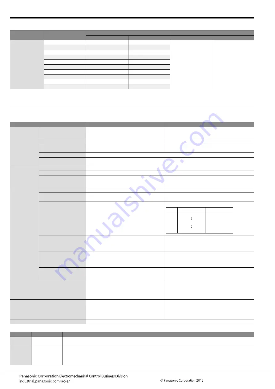
PRODUCT TYPES
Notes: 1. Order unit:
For volume production: 1-inner carton (1-reel) units
For samples, please contact our sales office.
2. Please contact us for connectors having a number of pins other than those listed above.
SPECIFICATIONS
1. Characteristics
2. Material and surface treatment
Mated height
Number of pins
Part number
Packing
Socket
Header
Inner carton (1-reel)
Outer carton
0.6mm
10
AXG7100J7
AXG8100J4
10,000 pieces
20,000 pieces
12
AXG7120J7
AXG8120J4
16
AXG7160J7
AXG8160J4
20
AXG7200J7
AXG8200J4
24
AXG7240J7
AXG8240J4
30
AXG7300J7
AXG8300J4
34
AXG7340J7
AXG8340J4
40
AXG7400J7
AXG8400J4
50
AXG7500J7
AXG8500J4
60
AXG7600J7
AXG8600J4
Item
Specifications
Conditions
Electrical
characteristics
Rated current
3.0A/pin contact (power terminal)
0.30A/pin contact (signal terminal): Max. 5 A at total
pin contacts
Rated voltage
60V AC/DC
Breakdown voltage
150V AC for 1 min.
No short-circuiting or damage at a detection current of 1 mA
when the specified voltage is applied for one minute.
Insulation resistance
Min. 1,000M
Ω
(initial)
Using 250V DC megger (applied for 1 min.)
Contact resistance
Max. 30m
Ω
(power terminal)
Max. 90m
Ω
(signal terminal)
Based on the contact resistance measurement method
specified by JIS C 5402.
Mechanical
characteristics
Composite insertion force
1.300N/pin contacts
×
pin contacts
Composite removal force
0.165N/pin contacts
×
pin contacts
Contact holding force
(Socket signal terminal,
Header power terminal)
Min. 0.20N/pin contacts
Measuring the maximum force.
As the contact is axially pull out.
Environmental
characteristics
Ambient temperature
–55
°
C to +85
°
C
No freezing at low temperatures. No dew condensation.
Storage temperature
–55
°
C to +85
°
C (product only)
–40
°
C to +50
°
C (emboss packing)
No freezing at low temperatures. No dew condensation.
Thermal shock resistance
(header and socket mated)
5 cycles,
insulation resistance min. 100M
Ω
,
contact resistance max. 30m
Ω
(power terminal)
max. 90m
Ω
(signal terminal)
Conformed to MIL-STD-202F, method 107G
Humidity resistance
(header and socket mated)
120 hours,
insulation resistance min. 100M
Ω
,
contact resistance max. 30m
Ω
(power terminal)
max. 90m
Ω
(signal terminal)
Conformed to IEC60068-2-78
Bath temperature 40
±
2
°
C,
humidity 90 to 95% R.H.
Saltwater spray resistance
(header and socket mated)
24 hours,
insulation resistance min. 100M
Ω
,
contact resistance max. 30m
Ω
(power terminal)
max. 90m
Ω
(signal terminal)
Conformed to IEC60068-2-11
Bath temperature 35
±
2
°
C,
saltwater concentration 5
±
1%
H
2
S resistance
(header and socket mated)
48 hours,
contact resistance max. 30m
Ω
(power terminal)
max. 90m
Ω
(signal terminal)
Bath temperature 40
±
2
°
C, gas concentration 3
±
1 ppm,
humidity 75 to 80% R.H.
Insertion and removal life
Mechanical life: 30 times
Contact resistance max. 30m
Ω
(power terminal)
max. 90m
Ω
(signal terminal)
Composite removal
force 0.165N/pin contacts
×
pin contacts
Repeated insertion and removal speed of max. 200 times/
hours
Soldering heat resistance
The initial specification must be satisfied electrically
and mechanically
Infrared reflow soldering: Peak temperature: 260
°
C or less
(on the surface of the PC board
around the connector terminals)
Soldering iron: 300
°
C within 5 sec.
350
°
C within 3 sec.
Unit weight
60 pin contacts: Socket 0.02g Header 0.01g
Part name
Material
Surface treatment
Molded
portion
LCP resin
(UL94V-0)
—
Contact and
Post
Copper alloy
Contact portion: Base: Ni plating, Surface: Au plating
Terminal portion: Base: Ni plating, Surface: Au plating (except the terminal tips)
The terminals close to the portion to be soldered have nickel barriers (exposed nickel portions).
Power terminals: Sockets: Base: Ni plating, Surface: Au plating (except the terminal tips)
Headers: Base: Ni plating, Surface: Au plating
Order Temperature (
°
C)
Time (minutes)
1
2
3
4
–55
85
–55
0
−
3
30
Max. 5
30
Max. 5
+
3
0
0
−
3


