


Narrow pitch connectors
A35US
with power terminal (0.35mm pitch)
–3–
ACCTB78E 201510-T
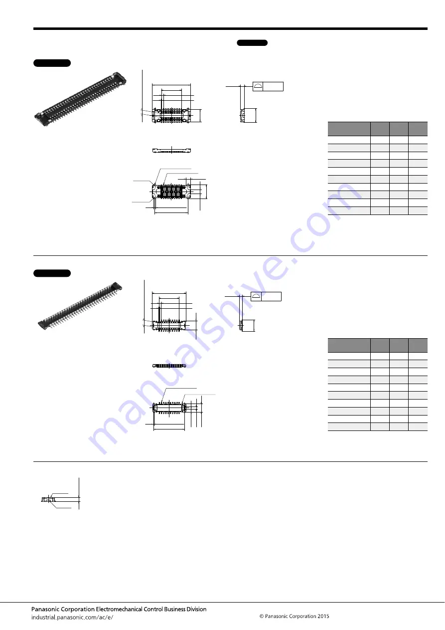
DIMENSIONS
(Unit: mm)
Socket (Mated height: 0.6 mm)
Header (Mated height: 0.6 mm)
Socket and Header are mated
The CAD data of the products with a
CAD Data
mark can be downloaded from: http://industrial.panasonic.com/ac/e/
Power terminal
Signal terminal
Z (Note)
Y (Note)
(Contact and Power terminal)
The degree of terminal flat
0.08
0.59
2.20
A
B
±
0.1
0.35
±
0.05
0.12
±
0.03
1.96
0.60 (Suction f
ace)
C
±
0.1
(0.68)
0.30
±
0.03
2.20
0.66
General tolerance:
±
0.2
Note: Since power terminals are built into the body, the Y and Z parts are connected electrically.
Dimension table (mm)
Number of pins/
dimension
A
B
C
10
4.25
1.40
3.45
12
4.60
1.75
3.80
16
5.30
2.45
4.50
20
6.00
3.15
5.20
24
6.70
3.85
5.90
30
7.75
4.90
6.95
34
8.45
5.60
7.65
40
9.50
6.65
8.70
50
11.25
8.40
10.45
60
13.00
10.15
12.20
CAD Data
A
B
±
0.1
0.35
±
0.05
0.12
±
0.03
The degree of terminal flat
0.46
1.80
1.42
0.80 (Suction f
ace)
(Post and Power terminal)
0.08
Power terminal
Signal terminal
(P
o
w
er ter
minal)
C
±
0.1
0.08
±
0.03
0.48
0.32
0.28
General tolerance:
±
0.2
Dimension table (mm)
Number of pins/
dimension
A
B
C
10
3.55
1.40
3.17
12
3.90
1.75
3.52
16
4.60
2.45
4.22
20
5.30
3.15
4.92
24
6.00
3.85
5.62
30
7.05
4.90
6.67
34
7.75
5.60
7.37
40
8.80
6.65
8.42
50
10.55
8.40
10.17
60
12.30
10.15
11.92
CAD Data
Header
Socket
0.60
±
0.1


