background image

Narrow pitch connectors 

A35US

 with power terminal (0.35mm pitch)

–5–

ACCTB78E   201510-T

NOTES

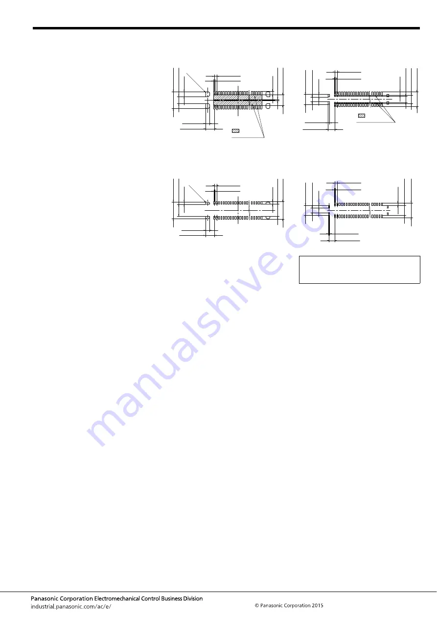
1. Design of PC board patterns

Conduct the recommended foot pattern 
design, in order to preserve the 
mechanical strength of terminal solder 
areas.

2. Recommended PC board and metal 
mask patterns

Connectors are mounted with high pitch 
density, intervals of 0.35 mm, 0.4 mm or 
0.5 mm.
In order to reduce solder and flux rise, 
solder bridges and other issues make 
sure the proper levels of solder is used.
The figures to the right are recommended 
metal mask patterns. Please use them as 
a reference.

• Socket (Mated height: 0.6 mm)

Recommended PC board pattern (TOP VIEW)

Recommended metal mask pattern

Metal mask thickness: When 100

μ

m

(Terminal opening ratio: 70%)

(Metal-part opening ratio: 46%)

• Header (Mated height: 0.6 mm)

Recommended PC board pattern (TOP VIEW)

Recommended metal mask pattern

Metal mask thickness: When 100

μ

m

(Signal terminal opening ratio: 70%)
(Power terminal opening ratio: 77%)

12

×

C0.15

0.35

±

0.03

0.20

±

0.03

2.50

±

0.03

1.60

±

0.03

0.20

±

0.03

(0.50)

1.04

±

0.03

(0.73)

0.60

±

0.03

1.325

±

0.03

: Insulatin 

area

(0.35)

8

×

C0.15

1.325

±

0.01

0.60

±

0.01

0.35

±

0.01

0.18

±

0.01

2.50

±

0.01

(0.39)

1.82

±

0.01

2.60

±

0.01

1.80

±

0.01

Please refer to the latest product 
specifications when designing your 
product.

0.35

±

0.03

0.20

±

0.03

0.26

±

0.03

1.045

±

0.03

1.48

±

0.03

(0.50)

0.90

±

0.03

1.20

±

0.03

2.20

±

0.03

(0.39)

0.70

±

0.03

: Insulatin 

area

0.20

±

0.01

0.885

±

0.01

0.35

±

0.01

0.18

±

0.01

1.48

±

0.01

(0.39)

1.42

±

0.01

2.20

±

0.01

0.70

±

0.01

(0.39)

Summary of Contents for AXG7100J7

Page 1: ...CATIONS Multiple connection of power signal between USB and battery in portable terminals such as smartphones and tablet PCs Socket 2 2m m 1 8m m Header RoHS compliant Socket 2 2mm 1 8mm Header Power terminals Specification 3 A in two locations 3 5mm 3 5mm Example Charging current Max 3 0 A 0 3 A pin Pitch 0 35 mm 20 pins signal terminals used Product without power terminals 20 pins signal termina...

Page 2: ...ng at low temperatures No dew condensation Thermal shock resistance header and socket mated 5 cycles insulation resistance min 100MΩ contact resistance max 30mΩ power terminal max 90mΩ signal terminal Conformed to MIL STD 202F method 107G Humidity resistance header and socket mated 120 hours insulation resistance min 100MΩ contact resistance max 30mΩ power terminal max 90mΩ signal terminal Conform...

Page 3: ...Y and Z parts are connected electrically Dimension table mm Number of pins dimension A B C 10 4 25 1 40 3 45 12 4 60 1 75 3 80 16 5 30 2 45 4 50 20 6 00 3 15 5 20 24 6 70 3 85 5 90 30 7 75 4 90 6 95 34 8 45 5 60 7 65 40 9 50 6 65 8 70 50 11 25 8 40 10 45 60 13 00 10 15 12 20 CAD Data A B 0 1 0 35 0 05 0 12 0 03 The degree of terminal flat 0 46 1 80 1 42 0 80 Suction face Post and Power terminal 0 ...

Page 4: ...Tape I 16 0 7 5 17 4 10 000 40 to 60 Tape I 24 0 11 5 25 4 10 000 Specifications for taping In accordance with JIS C 0806 3 1999 However not applied to the mounting hole pitch of some connectors Specifications for the plastic reel In accordance with EIAJ ET 7200B Leading direction after packaging 1 75 B A 2 0 4 0 4 0 0 3 0 1 1 5 d i a 0 1 0 Tape I Top cover tape Embossed carrier tape Embossed moun...

Page 5: ...tern TOP VIEW Recommended metal mask pattern Metal mask thickness When 100μm Terminal opening ratio 70 Metal part opening ratio 46 Header Mated height 0 6 mm Recommended PC board pattern TOP VIEW Recommended metal mask pattern Metal mask thickness When 100μm Signal terminal opening ratio 70 Power terminal opening ratio 77 1 2 C 0 1 5 0 35 0 03 0 20 0 03 2 50 0 03 1 60 0 03 0 20 0 03 0 50 1 04 0 03...

Page 6: ... dimensions given 5 PC board Control the thicknesses of the coverlay and adhesive to prevent poor soldering This connector has no stand off Therefore minimize the thickness of the coverlay etc so as to prevent the occurrence of poor soldering 6 For all connectors of the narrow pitch series to prevent the PC board from coming off during vibrations or impacts and to prevent loads from falling direct...

Page 7: ...ctor before mounting 9 Consult us when using a screen printing thickness other than that recommended Hand soldering 1 Set the soldering iron so that the tip temperature is less than that given in the table below Table A 2 Do not allow flux to spread onto the connector leads or PC board This may lead to flux rising up to the connector inside 3 Touch the soldering iron to the foot pattern After the ...

Page 8: ...ring avoid storing the connectors in areas of high humidity 2 Depending on the connector type the color of the connector may vary from connector to connector depending on when it is produced Some connectors may change color slightly if subjected to ultraviolet rays during storage This is normal and will not affect the operation of the connector 3 When storing the connectors with the PC boards asse...

Page 9: ...ne connectors are delivered in 50 piece units in the condition given right Consult a sale representative for ordering sample units Condition when delivered from manufacturing Required number of products for sample production Unit 50 pcs Embossed tape amount required for the mounting Reel Delivery can also be made on a reel by customer request Please refer to the latest product specifications when ...

Reviews: