background image

Notes on Using Narrow pitch Connectors/Stacking Connectors for High Current

–8–

ACCTB48E   201503-T

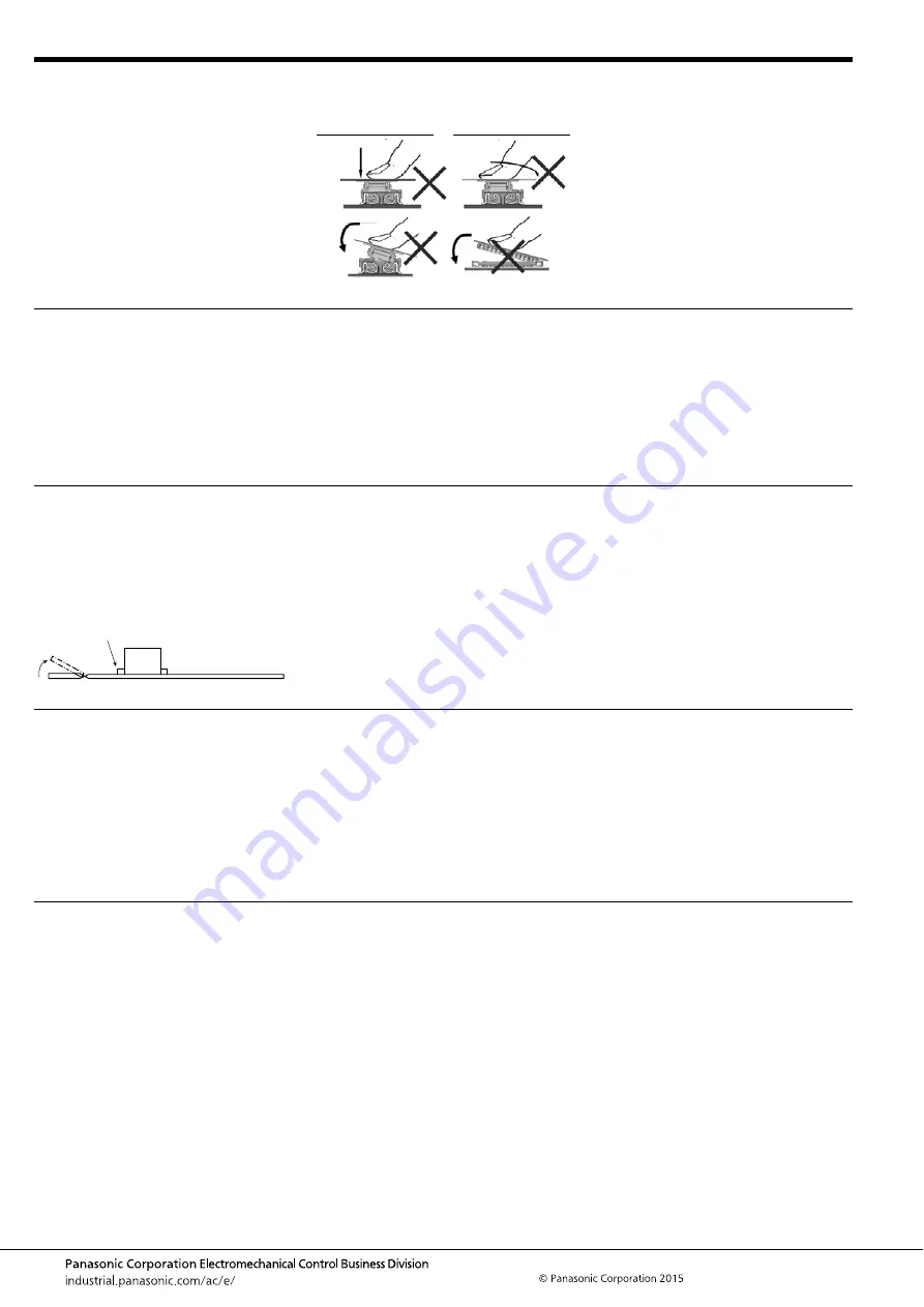
Precautions for mating

Cleaning flux from PC board

Handling the PC board

Storage of connectors

Other Notes

This product is designed with ease of 
handling. However, in order to prevent the 
deformation or damage of contacts and 
molding, take care and do not mate the 
connectors as shown right.

Strongly pressed and twisted

Tilted mating

Press-fitting while the mating 
inlets of the socket and 
header are not matched.

There is no need to clean this product.
If cleaning it, pay attention to the 
following points to prevent the negative 
effect to the product.
1) Keep the cleaning solvent clean and 
prevent the connector contacts from 
contamination.

2) Some cleaning solvents are strong and 
they may dissolve  the molded part and 
characters, so pure water passed liquid 
solvent is recommended.

 Handling the PC board after 

mounting the connector

When cutting or bending the PC board 
after mounting the connector, be careful 
that the soldered sections are subjected 
to excessive force.

The soldered areas should not be subjected to force.

1) To prevent problems from voids or air 
pockets due to heat of reflow soldering, 
avoid storing the connectors in areas of 
high humidity.
2) Depending on the connector type, the 
color of the connector may vary from 
connector to connector depending on 
when it is produced.

Some connectors may change color 
slightly if subjected to ultraviolet rays 
during storage. This is normal and will not 
affect the operation of the connector.
3) When storing the connectors with the 
PC boards assembled and components 
alreeady set, be careful not to stack them 
up so the connectors are subjected to 

excessive forces.
4) Avoid storing the connectors in 
locations with excessive dust. The dust 
may accumulate and cause improper 
connections at the contact surfaces.

1) Do not remove or insert the electrified 
connector (in the state of carrying current 
or applying voltage).
2) Dropping of the products or rough 
mishandling may bend or damage the 
terminals and possibly hinder proper 
reflow soldering.
3) Before soldering, try not to insert or 
remove the connector more than 
absolutely necessary.

4) When coating the PC board after 
soldering the connector to prevent the 
deterioration of insulation, perform the 
coating in such a way so that the coating 
does not get on the connector.
5) There may be variations in the colors 
of products from different production lots. 
This is normal.
6) The connectors are not meant to be 
used for switching.

7) Product failures due to condensation 
are not covered by warranty.

Summary of Contents for AXG7100J7

Page 1: ...CATIONS Multiple connection of power signal between USB and battery in portable terminals such as smartphones and tablet PCs Socket 2 2m m 1 8m m Header RoHS compliant Socket 2 2mm 1 8mm Header Power terminals Specification 3 A in two locations 3 5mm 3 5mm Example Charging current Max 3 0 A 0 3 A pin Pitch 0 35 mm 20 pins signal terminals used Product without power terminals 20 pins signal termina...

Page 2: ...ng at low temperatures No dew condensation Thermal shock resistance header and socket mated 5 cycles insulation resistance min 100MΩ contact resistance max 30mΩ power terminal max 90mΩ signal terminal Conformed to MIL STD 202F method 107G Humidity resistance header and socket mated 120 hours insulation resistance min 100MΩ contact resistance max 30mΩ power terminal max 90mΩ signal terminal Conform...

Page 3: ...Y and Z parts are connected electrically Dimension table mm Number of pins dimension A B C 10 4 25 1 40 3 45 12 4 60 1 75 3 80 16 5 30 2 45 4 50 20 6 00 3 15 5 20 24 6 70 3 85 5 90 30 7 75 4 90 6 95 34 8 45 5 60 7 65 40 9 50 6 65 8 70 50 11 25 8 40 10 45 60 13 00 10 15 12 20 CAD Data A B 0 1 0 35 0 05 0 12 0 03 The degree of terminal flat 0 46 1 80 1 42 0 80 Suction face Post and Power terminal 0 ...

Page 4: ...Tape I 16 0 7 5 17 4 10 000 40 to 60 Tape I 24 0 11 5 25 4 10 000 Specifications for taping In accordance with JIS C 0806 3 1999 However not applied to the mounting hole pitch of some connectors Specifications for the plastic reel In accordance with EIAJ ET 7200B Leading direction after packaging 1 75 B A 2 0 4 0 4 0 0 3 0 1 1 5 d i a 0 1 0 Tape I Top cover tape Embossed carrier tape Embossed moun...

Page 5: ...tern TOP VIEW Recommended metal mask pattern Metal mask thickness When 100μm Terminal opening ratio 70 Metal part opening ratio 46 Header Mated height 0 6 mm Recommended PC board pattern TOP VIEW Recommended metal mask pattern Metal mask thickness When 100μm Signal terminal opening ratio 70 Power terminal opening ratio 77 1 2 C 0 1 5 0 35 0 03 0 20 0 03 2 50 0 03 1 60 0 03 0 20 0 03 0 50 1 04 0 03...

Page 6: ... dimensions given 5 PC board Control the thicknesses of the coverlay and adhesive to prevent poor soldering This connector has no stand off Therefore minimize the thickness of the coverlay etc so as to prevent the occurrence of poor soldering 6 For all connectors of the narrow pitch series to prevent the PC board from coming off during vibrations or impacts and to prevent loads from falling direct...

Page 7: ...ctor before mounting 9 Consult us when using a screen printing thickness other than that recommended Hand soldering 1 Set the soldering iron so that the tip temperature is less than that given in the table below Table A 2 Do not allow flux to spread onto the connector leads or PC board This may lead to flux rising up to the connector inside 3 Touch the soldering iron to the foot pattern After the ...

Page 8: ...ring avoid storing the connectors in areas of high humidity 2 Depending on the connector type the color of the connector may vary from connector to connector depending on when it is produced Some connectors may change color slightly if subjected to ultraviolet rays during storage This is normal and will not affect the operation of the connector 3 When storing the connectors with the PC boards asse...

Page 9: ...ne connectors are delivered in 50 piece units in the condition given right Consult a sale representative for ordering sample units Condition when delivered from manufacturing Required number of products for sample production Unit 50 pcs Embossed tape amount required for the mounting Reel Delivery can also be made on a reel by customer request Please refer to the latest product specifications when ...

Reviews: