


Stacking connector for high current
B01
–3–
ACCTB71E 201412-T
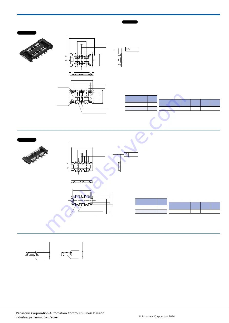
DIMENSIONS
(Unit: mm)
Socket (Mated height: 0.6 mm and 0.8 mm)
Header (Mated height: 0.6 mm and 0.8 mm)
Socket and Header are mated
The CAD data of the products with a
CAD Data
mark can be downloaded from: http://industrial.panasonic.com/ac/e/
0.08
0.50 (Suction f
ace)
2.40
0.86
The degree of terminal flat
(Contact and soldering terminals)
Y (Note 1)
Z (Note 1)
Signal contact (2 pins)
Power contact (4 pins)
0.18
±
0.03
0.20
±
0.03
D
±
0.1
C
±
0.1
0.58
±
0.03
0.14
±
0.03
E
2.16
B
±
0.1
A
General tolerance:
±
0.2
Note: 1. Because the soldering terminal Y and Z are the unified structure, they are connected electrically.
Dimension table (mm)
Number of pins/
dimension
A
B
C
D
6
4.45
1.60
3.85
3.12
Mated height/
dimension
E
0.6mm
0.59
0.8mm
0.79
CAD Data
0.08
1.51
(0.34)
0.88
The degree of terminal flat
(Post and soldering terminals)
Signal contact (2 pins)
Power contact (4 pins)
(Solder
ing
ter
minal)
C
±
0.1
0.20
±
0.03
0.70
±
0.03
0.14
±
0.03
B
±
0.1
A
D
0.70 (Suction f
ace)
General tolerance:
±
0.2
Dimension table (mm)
Number of pins/
dimension
A
B
C
6
3.76
1.60
3.26
Mated height/
dimension
D
0.6mm
0.47
0.8mm
0.65
CAD Data
Socket
Header
0.60
±
0.1
Socket
Header
0.80
±
0.1


