68
BL-C111A /BL-C131A
14.5. I/O Board (Component View)
BL-C111A/BL-C131A I/O BOARD
C6
C16
BOND LOCK
X1
C18
C5
C7
C4
C14
SA1
T1
SA4
R8
R5
2
1
R6
R9
L11
L10
C10
SA2
8
5
1
C17
R4
R3
R13
R15
L4
L13
L2
R14
D5
R11
D4
L3
D1
C1
CN3
C13
L1
8
C12
L12
7
16
1
8
9
CN2
CN1
2
2
1
1
3
3
IC2
IC3
IC1
10
R12
C15
C8
SA3
C11
R2
D6
1
20
C3
C2
11
D3
R10
Summary of Contents for BL C131A - Network Camera - Pan
Page 5: ...5 BL C111A BL C131A LENS BOARD I O BOARD ...
Page 17: ...17 BL C111A BL C131A 5 Location of Controls and Components ...
Page 18: ...18 BL C111A BL C131A 6 Installation Instructions ...
Page 19: ...19 BL C111A BL C131A ...
Page 21: ...21 BL C111A BL C131A 7 2 Connection ...
Page 25: ...25 BL C111A BL C131A 1 It does not turn on when LED mode is OFF on web setup menu ...
Page 26: ...26 BL C111A BL C131A 8 2 Indicator view Check ...
Page 27: ...27 BL C111A BL C131A 8 3 LAN Block Check 8 3 1 Green Light On ...
Page 28: ...28 BL C111A BL C131A 8 3 2 Orange Light Blinking 1 ...
Page 29: ...29 BL C111A BL C131A 8 3 3 Orange Light Blinking 2 ...
Page 30: ...30 BL C111A BL C131A 8 4 Camera Block Check ...
Page 31: ...31 BL C111A BL C131A 8 5 Power Supply Block Check ...
Page 33: ...33 BL C111A BL C131A 8 7 Pyroelectric Infrared Sensor Check ...
Page 34: ...34 BL C111A BL C131A 8 8 Sound Block Check ...
Page 35: ...35 BL C111A BL C131A 8 9 RF Block Check BL C131A ...
Page 64: ...64 BL C111A BL C131A M O1 O2 O3 P1 P2 P3 N1 N2 Power ON Start ...
Page 73: ...73 BL C111A BL C131A 16 2 Cabinet and Electrical Parts Location BL C131A ...
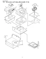
Page 74: ...74 BL C111A BL C131A 16 3 Accessories and Packing Materials BL C111A ...
Page 75: ...75 BL C111A BL C131A 16 4 Accessories and Packing Materials BL C131A ...


