Operating procedure
If the heater operation test fails, check the following:
2 TROUBLESHOOTING CHART
Note :
The causes of unsuccessful baking vary and can be divided roughly into user-side problems and bread maker problems. Most
problems are caused by the user. Therefore, it is very important to obtain detailed information from customers regarding their
conditions of using the bread maker and to specify whether the problem lies with the user or the bread maker.
Before establishing the "Main Body Test Mode", plug in the power cord to check the following.
* When "H01" appears on the LCD, it indicates thermistor breakage failure. (Replace the thermistor.)
1. The LCD shows "0:00".
2. When the "select", "Option", "Size", "Crust", "Timer", or "Stop/Start" pad is pressed, a buzzer sounds to ask if the command
may be accepted.
3. When "0:00" does not appear on the LCD or the buzzer does not sound when operation keys are pressed, check the
following.
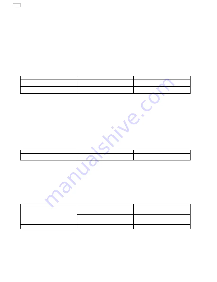
Check point
Diagnosis
Remedy
Electric connection
Check that the terminal and connectors are
connected properly.
Connect them properly.
Power cord
Check the continuity of the power cord.
Replace the power cord.
Thermal fuse
Check the continuity of the thermal fuse.
Replace the thermal fuse.
* Only units of ENG specification have a thermal fuse in the power cord and need to be checked.
2.1. Main Body Test Mode
2.1.1. Setting the Main Body Initial Test Modes
1. Insert the power cord plug into an electrical outlet.
2. Press the "select", "Option" and "Size" pads all at the same time.
3. When all indications on the LCD are illuminated, the main body test waiting mode has been set successfully.
* When some or all of the indications do not appear on the LCD, follow steps 1 and 2.
* Pressing the "Stop/Start" pad returns you to the normal initial mode. (To be pressed when the test is finished.)
When the initial test mode cannot be set, the main body is experiencing a problem.
Check point
Diagnosis
Remedy
Control board A, B
If no problem is found with the power cord and
thermal fuse
Replace control board A and B.
2.1.2. Motor and Solenoid Operation Test
1. Make sure that the main body is in the main body test waiting mode. Press the "Crust" pad.
2. The LED is illuminated with "REST" and other characters shown on the display.
3. The solenoid runs for 1 second and stops for 1 second. Then, the motor runs for 0.2 seconds and stops for 1.8 seconds. This
procedure is repeated twice before continuous running starts.
4. The motor and solenoid stop running 10 minutes later and enter the main body test waiting mode.
5. Pressing the "Stop/Start" pad always returns you to the main body test waiting mode.
If the motor and solenoid operation test fails, check the following.
Check point
Diagnosis
Remedy
The solenoid does not operate.
Check the continuity. (Resistance: approx.
540
Ω
)
Replace the solenoid.
Replacing the solenoid does not solve the
problem.
Replace control board A and B.
The motor does not rotate.
Check the continuity.
Replace the motor.
The motor runs but the blades do not rotate.
Check that the belt is not disconnected.
Replace the belt.
2.1.3. Heater Operation Test
1. Make sure that the main body is in the main body test waiting mode. Press the "Option" pad.
2. The LED is illuminated with "TEMP" and "POWER ALERT" shown on the display.
3. Power the heater and turn it off when the sensor temperature reaches 165°C.
4. Pressing the "Stop/Start" pad always returns you to the main body test waiting mode.
8
SD-253
Summary of Contents for Bread Bakery SD-253
Page 2: ...1 Operating Instructions 2 SD 253 ...
Page 3: ...3 SD 253 ...
Page 4: ...4 SD 253 ...
Page 5: ...5 SD 253 ...
Page 6: ...6 SD 253 ...
Page 7: ...7 SD 253 ...
Page 23: ...5 1 Parts Location ENG 5 REPLACEMENT PARTS ENG 23 SD 253 ...
Page 25: ...6 REPLACEMENT PARTS GER 6 1 Parts Location GER 25 SD 253 ...
Page 27: ...7 REPLACEMENT PARTS BEL 7 1 Parts Location BEL 27 SD 253 ...
Page 29: ...8 1 Parts Location RSA 8 REPLACEMENT PARTS RSA 29 SD 253 ...
Page 31: ...9 REPLACEMENT PARTS AUST 9 1 Parts Location AUST 31 SD 253 ...
Page 33: ...10 REPLACEMENT PARTS NZL 10 1 Parts Location NZL 33 SD 253 ...


