


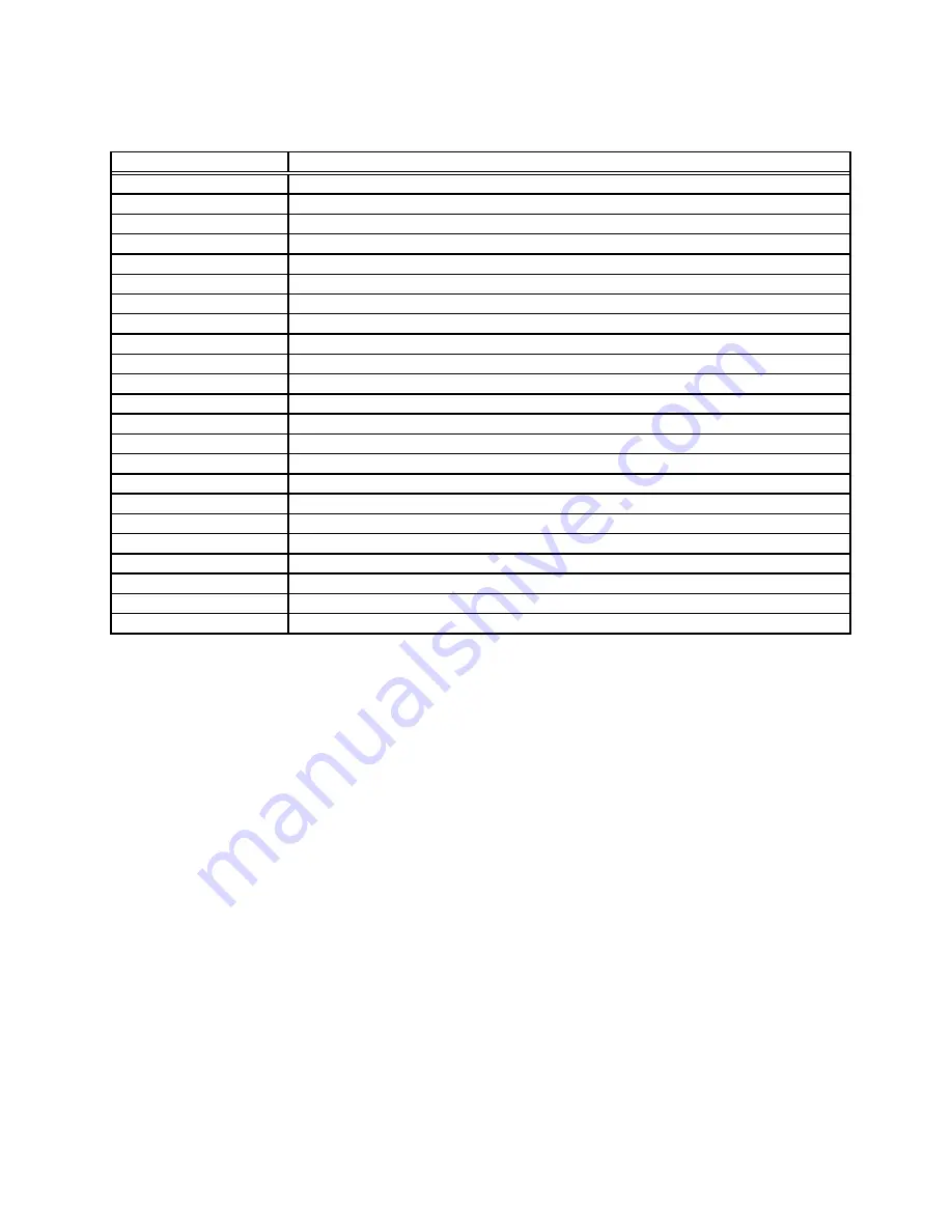
Address
Function
x0778 - x077F
ECP Printer Port (LPT1)
x0CF8 - x0CFF
PCI bus
x1000 - x107F
Motherboard resources
x1080 - x10BF
Ricoh RL5C476 CardBus Controller
x1080 - x10BF
PRISM2 IEEE 802.11 PC CARD Adapter
x10D0 - x10DF
Ricoh RL5C476 CardBus Controller
x10D0 - x10DF
HITACHI ATA FlashDisk
x10E0 - x10EF
Intel(R) 82801BA/BAM SMBus Controller - 2443
x1170 - x1177
Alias of Intel(R) 82801BAM Ultra ATA Storage Controller - 244A
x1170 - x1177
Alias of Secondary IDE controller (dual fifo)
x1180 - x11BF
Motherboard resources
x1400 - x14FF
Crystal WDM Audio Codec
x1800 - x1807
Primary IDE controller (dual fifo)
x1800 - x180F
Intel(R) 82801BAM Ultra ATA Storage Controller - 244A
x1808 - x180F
Secondary IDE controller (dual fifo)
x1820 - x183F
Intel(R) 82801BA/BAM USB Universal Host Controller - 2442
x1840 - x187F
Crystal WDM Audio Codec
xE000 - xE03F
Motherboard resources
xE040 - xE07F
Motherboard resources
xE080 - xE0BF
Motherboard resources
xE0C0 - xE0FF
Motherboard resources
xE100 - xE107
Motherboard resources
xFE00 - xFE01
Motherboard resources
10-2
Summary of Contents for CF-07 Series
Page 3: ... RU 8 6 1 2 2 ...
Page 4: ...2 3 ...
Page 21: ...9 6 System Memory Map ...
Page 24: ...8 Diagnosis Procedure Basic Procedures 11 ...
Page 41: ...Example ALT F brings up the File menu Input screen Order of test flow selection 16 5 ...
Page 43: ...14 Wiring Connection Diagram 17 ...
Page 47: ...16 Exploded View 1 Exploded View 1 2 19 1 ...
Page 48: ...2 Exploded View 2 2 19 2 ...
Page 64: ......
Page 65: ......
Page 66: ......
Page 67: ......
Page 68: ......
Page 69: ......
Page 70: ...CF 07LZ5ZYXM 1 Schematic Diagrams Upper Main 1 CPU 1 2 ...
Page 71: ...Upper Main 2 CPU 2 2 2 ...
Page 72: ...U s 3 pper Main 3 Resister ...
Page 73: ...U k 4 pper Main 4 Cloc ...
Page 74: ...U 5 pper Main 5 GMCH M 1 2 ...
Page 75: ...pper Main 6 GMCH M 2 2 U U 6 ...
Page 76: ...pper Main 7 ON Board Memory 7 U U ...
Page 77: ...pper Main 8 Micro DIMM 8 U U ...
Page 78: ...Upper Main 9 iCH2 M 1 2 9 ...
Page 79: ...Upper Main 10 iCH2 M 2 2 10 U U ...
Page 80: ...pper Main 11 Terminator 11 U U ...
Page 81: ...U Upper Main 12 HDD 12 ...
Page 82: ...Upper Main 13 BIOS 13 U U ...
Page 83: ...Upper Main 14 PCMCIA Controller 14 ...
Page 84: ...pper Main 15 Slot 1 WLSD Connector 15 U U ...
Page 85: ...pper Main 16 LED Connector 16 U ...
Page 86: ...Upper Main 17 Base Connector 17 ...
Page 87: ...Upper Main 18 VCPUCORE VC25 18 ...
Page 88: ...pper Main 19 Power Circuit 19 U U ...
Page 89: ...Upper Main 20 Modem Controller 20 ...
Page 90: ...pper Main 21 Line Codec 21 U U ...
Page 91: ...Lower Main 1 Connector 22 L L ...
Page 92: ...ower Main 2 Super I O 23 L ...
Page 93: ...Lower Main 3 COM Connector 24 L L ...
Page 94: ...Lower Main 4 Wireless Connector 25 L L ...
Page 95: ...Lower Main 5 KBC 26 L L ...
Page 96: ...Lower Main 6 Q AW for Doc 27 L L ...
Page 97: ...Lower Main 7 Doc Connector 28 ...
Page 98: ...Lower Main 8 EC 29 ...
Page 99: ...L LLower Main 9 Reset 30 ...
Page 100: ...L Lower Main 10 DC IN 31 ...
Page 101: ...L Lower Main 11 VD3 VD5 32 ...
Page 102: ...L Lower Main 12 Power Circuit2 33 ...
Page 103: ...L Lower Main 13 BATT SW 34 ...
Page 104: ...Lower Main 14 RF DC DC 35 ...
Page 105: ...Lower Main 15 Charger 36 ...
Page 106: ...Lower Main 16 Doc Power 37 ...
Page 107: ...Lower Main 17 VD18 38 ...
Page 108: ...Serial Connector 39 S S ...
Page 109: ...D U Sub Connector 40 D DDD ...
Page 110: ...D U Docking Connector 41 D DD ...
Page 111: ...D U Sub Connector 42 D D ...
Page 112: ...43 ...
Page 113: ...44 ...
Page 114: ...45 ...
Page 115: ...W W 46 ...
Page 116: ...Wireless 5 RF IF Mixer 1st Lo 47 ...
Page 117: ...48 ...


