13. Disassembly/Reassembly
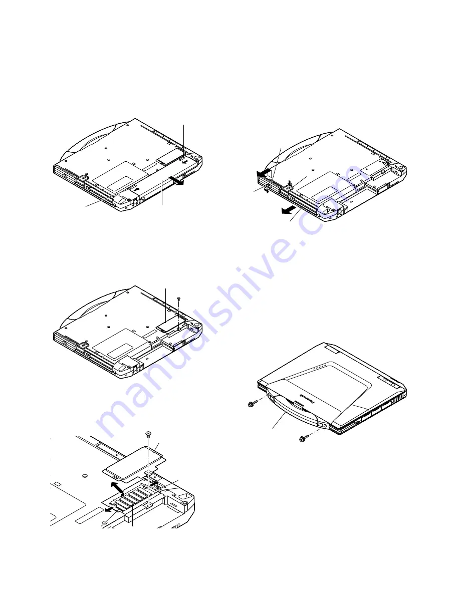
13.1 Removing the Battery Pack.
13.2 Removing the RAM Card.
1. Slide the Latch 1 to unlock.(
1
)
2. Slide the Latch 2 (
2
), and then without releasing it,
slide and remove the Battery Pack.(
3
)
Note: Power off the computer. Do not shut down to the Suspend or hibernation mode.
Do not add peripherals while the computer is in the Suspend or hibernation mode;
abnormal operation may result.
1. Remove the screw <A>, and remove the RAM
Card Cover.
Screw <A>: DXSB2+6FZL
2. Open the Hooks outward (
1
), and remove the RAM
Card.(
2
)
13.3 Removing the HDD Unit and
the DVD-ROM Drive Unit.
HDD Unit
1. Slide the Latch to unlock.(
1
)
2. Lift up the cover of the HDD Unit, and then without
releasing it, slide the HDD Unit. (
2
)
DVD-ROM Drive Unit
1. Push the Button (
3
), and then without releasing it,
slide the DVD-ROM Drive Unit.(
4
)
13.4 Removing the Handle Unit.
1.
Remove the two screws <B>, and remove the
Handle Unit.
Screw <B>: DXYN4+J12FZL
30
1
2
3
Latch 1
Latch 2
Battery Pack
1
2
1
RAM Card Cover
Hook
Hook
RAM Card
1
2
3
4
Button
HDD Unit
DVD-ROM Drive Unit
Latch
Handle Unit
<B>
<B>
RAM Card Cover
<A>
Summary of Contents for CF-73ECLTXKM - Toughbook 73 - Pentium M 1.4...
Page 2: ...2 1 ...
Page 4: ...2 3 ...
Page 5: ...2 4 ...
Page 7: ...1 Specfication 4 ...
Page 8: ......
Page 11: ...3 Block Diagram System Confugration Diagram 8 ...
Page 12: ...4 9 ...
Page 14: ...6 11 ...
Page 56: ...1 2 3 4 5 6 7 8 9 10 11 A B C D E F G H I J CF 73E3 Printed Circuit Board Main PCB Top View ...
Page 57: ...1 2 3 4 5 6 7 8 9 10 11 A B C D E F G H I J Main PCB Bottom View ...
Page 58: ...1 2 3 4 5 6 7 8 9 10 11 A B C D E F G H I J VGA PCB Top View VGA PCB Bottom View ...
Page 59: ...Rear PCB Top View Rear PCB Bottom View 1 2 3 4 5 6 7 8 9 10 11 A B C D E F G H I J ...


