background image

Page 1-59

REGULAR

MAINTENANCE

1

Check Every 140 Hours (Once a Week)

1-4-7

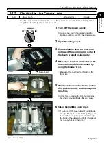
Cleaning the Line Camera Lens

If such as chips and dust adhere to the lens of the line camera, a nozzle looks as if it tapered or a
recognition error of chip components can occur.

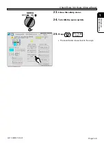
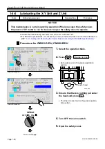
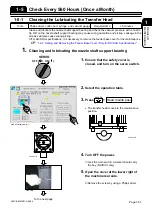
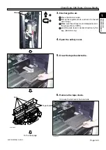
1.

Turn OFF the power supply.

 Because the cooling fan located under the

lighting is rotating, turn OFF the power supply.

2.

Open the safety cover.

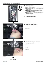
3.

Ensure that the head and nozzle do
not lower. While holding the center of
the beam, press it inside gently.

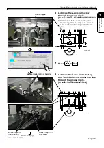
4.

Blow away the dust from between the
illumination and the line camera by
using the blower brush.

• Blow away the dust from the left side or the

front side.

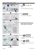
Tools

Blower brush

Required time

5 minutes

OFF (     ) ON (    ) 

SERVO

444C-490P

Blower brush

444C-E-MMA01-A08-06

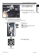
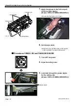
5.

Wind a cloth around a stick or such a
thin plate as a ruler, and then wipe the
lens face.

 At this time, removing the NG chip discharge

box and its mount will make this work easy.

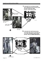
6.

Clean the lighting cover glass.

 If the inside of the cover glass of the lighting is

heavily stained, detach the black lighting cover,
remove the cover glass holder, and then wipe
the inside of the glass with a cloth. (Be careful
not to apply forces to the glass.)

444C-518P

444C-519P

Summary of Contents for CM201-D

Page 1: ...asing CM202 the modular high speed placement machine Before placing the machine in service be sure to read the instruction manual for proper usage After that store it carefully and it if necessary 4U4C E MMAB 0010 Modular High Speed Placement Machine CM202 Maintenance Manual 2 2 ...

Page 2: ......

Page 3: ...u city Saga Japan TEL 81 942 84 2644 FAX 81 942 84 2636 For Service and Supply of Spares in Europe you may contact Panasonic Europe Continental Europe PFAE Panasonic Factory Automation Europe Winsbergring 15 22525 Hamburg Germany Phone number 0049 0 40 85386 321 Fax number 0049 0 40 85386 332 United Kingdom PIEL Panasonic Industrial Europe U K Panasonic House Willoughby Road Bracknell Berks RG12 8...

Page 4: ...a h p 3 e g a t l o v l a m r o N V 0 1 z H 0 6 0 5 y c n e u q e r F V 0 2 2 C A s e s a h p 3 r o z H 0 6 y c n e u q e r F V 1 1 V 0 0 4 C A s e s a h p 3 e g a t l o v l a m r o N V 0 1 z H 0 6 0 5 y c n e u q e r F r e w o P A V k 5 1 A V k 5 2 A V k 5 1 A V k 5 2 r i a y l p p u S e r u s s e r p d r a w r e t f a t i n U R M e h t r o f a P M 4 5 0 o t a P M 9 4 0 a P M 8 7 0 o t a P M 9 4 ...

Page 5: ...nd engineers of the machine It describes the operating procedure precautions and information which is necessary for safe and effective operation Operating Manual This manual This manual is for the persons who maintain the machine It describes simple inspection adjustment and replacement of consumable parts Troubleshooting is also described Maintenance Manual 1 2 2 2 The assembly of each unit is in...

Page 6: ...4 4U4C E MMA00 B01 00 MEMO ...

Page 7: ...5 1 2 3 Maintenance Manual 4U4C E MMA00 A02 16 SAFETY PRECAUTIONS REGULAR MAINTENANCE MACHINE PARAMETER SOLUTIONS FOR ERROR APPENDIX ...

Page 8: ...x after Operation 1 22 1 3 5 Cleaning the Used Tape Box after Operation 1 22 1 4 Check Every 140 Hours Once a Week 1 24 1 4 1 Cleaning the Color Touch Panel 1 24 1 4 2 Cleaning and Lubricating the Tape Feeder Table 1 25 1 4 3 Cleaning and Lubricating the Nozzle 1 28 1 4 4 Cleaning the Support Pin Batch Exchange Table 1 42 1 4 5 Checking and Lubricating the Board Conveyor 1 44 1 4 6 Lubricating the...

Page 9: ...ing Consumable Parts 1 94 1 10 1 Replacing Color Touch Panel Back Light 1 94 Chapter 2 MACHINE PARAMETER 2 1 Machine Parameter 2 2 2 1 1 Origin offset 2 3 2 1 2 Judgment Value 2 4 2 1 3 Nozzle Mount Pickup Position 2 5 2 1 4 Nozzle Height 2 5 2 1 5 Optional Setting 2 6 2 1 6 Moving Parameter Setting 2 7 2 1 7 Nozzle Changer 2 7 2 1 8 Heat Calibration Mark 2 8 2 1 9 Mount Position 2 8 2 1 10 Board ...

Page 10: ...2 6 DC down 3 12 3 2 7 Self Diagnosis Error 3 16 3 2 8 Nozzle Setting Error 3 18 3 2 9 Returning from Power Interruptions Occurred during Operation 3 24 3 3 Load Arrangement 3 25 3 3 1 Load Arrangement of CM202 3 25 3 3 2 Load Arrangement of CM201 3 27 3 3 3 Load Arrangement of CM202 DS 3 29 3 3 4 Load Arrangement of CM201 DS 3 32 3 4 Load List 3 36 3 4 1 Load List of CM202 3 36 3 4 2 Load List of...

Page 11: ... B 6 LOAD WIRING DIAGRAM EXTENSION CONVEYOR 2 B 7 LOAD WIRING DIAGRAM ONLY FOR DHU SPECIFICATIONS Appendix C CONTROL BOX C 1 CPU BOX C 2 CPU BOX ONLY FOR DHU SPECIFICATIONS C 3 POWER BOX Appendix D SET UP DIAGRAM Appendix E WHOLE CONNECTION DIAGRAM ONLY FOR EUROPEAN SPECIFICATIONS Appendix F OPTION F 1 CONVEYOR SPEED CONTROL UNIT F 2 CONVEYOR SPEED CONTROL UNIT SETUP DIAGRAM F 3 CONVEYOR SPEED CON...

Page 12: ...10 4U4C E MMA00 A02 01 MEMO ...

Page 13: ...s are only some examples of the symbolic indications This indication refers to a situation which is considered that there is imminent danger of death or serious injury This indication refers to a situation which is considered that there is a possibility of death or serious injury This indication refers to a situation which is considered that there is a possibility of only injury or physical damage...

Page 14: ...rve DANGER 444C E XXA00 A03 01 L06EB DO NOT OPEN THE COVER WHEN OPER ATING You will have serious injury if you touch the active part inside L02E DO NOT TOUCH AC TIVE PART WHEN OPERATING You will have serious injury if you touch the active part ...

Page 15: ... There are two emergency stop buttons on CM201 D DU DH DS Pressing any one of them stops operation Press the nearest one Remove the cause of the danger or abnormality then re start operation To reset the emergency stop button pull the button M107E 1 Emergency stop button At the front side 2 Emergency stop button At the rear side CM201 D DU DH DS As for the explanation the illustration of CM201 DH ...

Page 16: ...rear right If you sense any danger or abnormality press an emergency stop button to stop the machine If you continue to operate the machine in a dangerous or abnormal state a breakdown or an accident will occur There are four emergency stop buttons on CM202 D DU Pressing any one of them stops operation Press the nearest one Remove the cause of the danger or abnormality then re start operation To r...

Page 17: ... occur There are two emergency stop buttons on CM202 DH DHU DK DS Pressing any one of them stops operation Press the nearest one Remove the cause of the danger or abnormality then re start operation To reset the emergency stop button pull the button CM202 DH DHU DK DS As for the explanation the illustration of CM202 DH is used 2 Emergency stop button At the rear side 1 Emergency stop button At the...

Page 18: ...art such as a sensor Disassembling or replacing parts Changing production board types or working for daily inspection Turn OFF the servo switch Placing a board onto the conveyor or removing one from there Setting production materials such as feeders M73EB 1 2 3 CM201 D DU DH DS As for the explanation the illustration of CM201 DH is used WARNING Cut off the power supplying to the machine Turn OFF t...

Page 19: ...or each kind of work Repairing such as a control BOX Cut off the power supplying to the machine Turning OFF the power supply routinely Turn OFF the power supply Replacing a control part such as a sensor Disassembling or replacing parts Changing production board types or working for daily inspection Turn OFF the servo switch Placing a board onto the conveyor or removing one from there Setting produ...

Page 20: ... the machine Turning OFF the power supply routinely Turn OFF the power supply Replacing a control part such as a sensor Disassembling or replacing parts Changing production board types or working for daily inspection Turn OFF the servo switch Placing a board onto the conveyor or removing one from there Setting production materials such as feeders 4U4C AA00 444C E XXA00 A03 02 1 2 3 1 2 RELEASE TRI...

Page 21: ...Page 9 SAFETY PRECAUTIONS Be sure to observe 444C E XXA00 A03 02 WARNING ...

Page 22: ...cause injury to the worker in front of the machine Make sure that no worker is in the front when machine starting L19EB M09E TAKE CARE NOT TO PINCH YOUR HANDS OR FINGERS You will have serious injury if your hands or fingers are caught in the conveyors during manual or automatic width adjustment TURN OFF THE SERVO SWITCH BE FORE PLACING A BOARD ON OR RE MOVING IT FROM THE CONVEYOR You will have ser...

Page 23: ...er carry out training by yourself or consult the manufacturer M62EB DO NOT TURN OFF THE SERVO SWITCH DURING OPERATION The machine may get out of control and injure you Before turning OFF the servo switch bring the machine to a temporary stop state such as a single stop state and a cycle stop state or an operation stop state M63E DO NOT MOVE ANY AXES INCLUD ING HEADS MANUALLY WHILE TURNING OFF AND ...

Page 24: ...ause fire because of generated heat Check the dissipation power in your Standard Specifica tion before consulting an electrical contractor M89EB M06E GROUND THE MA CHINE PROPERLY There is a risk of an electric shock or leak Consult a professional electrical contractor 444C E XXA00 A03 01 DO NOT DAMAGE POWER AND OTHER CORDS OR PLUGS Damaged cord and plug may cause electric shock short circuit or fi...

Page 25: ...LOSING THE COVER Your hands or fingers may be caught in the cover and injured M24EB TAKE AWAY TOOLS FROM THE INSIDE OF THE MACHINE The machine may malfunction as a result of a tool left inside Before operating the ma chine verify that no tools are left inside M18E DO NOT CLIMB OR RIDE ON THE MA CHINE You may fall from or get caught in the machine and get injured ONLY THE PERSON IN CHARGE MUST CHAN...

Page 26: ...age to the boards or the ma chine If there are any boards or other objects on the conveyor turn OFF the servo switch and remove them M36E M20EB DO NOT BLOCK OFF THE OUTLET OR INLET OF THE FAN The temperature inside the machine will rise and the machine may act abnormally And it may injure you Do not block off the outlet or inlet of the fan Periodically clean the filters of the outlet and inlet M44...

Page 27: ... this machine Follow the instructions on each label If a label has come off put a new one on a proper position To order a label from the manufacturer refer to PARTS LIST M32E 444C E XXA00 A04 03 The labels for safety pasted on the product The positions of danger labels on the front side Label part No E24C AA00 ...

Page 28: ... this machine Follow the instructions on each label If a label has come off put a new one on a proper position To order a label from the manufacturer refer to PARTS LIST The positions of warning labels on the front side The labels for safety pasted on the product 444C E XXA00 A04 02 Label part No E24C AA00 Inside ...

Page 29: ... this machine Follow the instructions on each label If a label has come off put a new one on a proper position To order a label from the manufacturer refer to PARTS LIST The positions of warning labels on the rear side The labels for safety pasted on the product 444C E XXA00 A04 06 Label part No E24C AB01 Inside ...

Page 30: ... each label If a label has come off put a new one on a proper position To order a label from the manufacturer refer to PARTS LIST The positions of warning labels on the front side The labels for safety pasted on the product 444C E XXA00 A04 04 The positions of warning labels on the rear side Label part No E24C AB01 E24C AA00 Inside Inside Inside Inside ...

Page 31: ...ructions on each label If a label has come off put a new one on a proper position To order a label from the manufacturer refer to PARTS LIST The positions of danger labels on the front side M32E E14C AA00 The labels for safety pasted on the product The positions of danger labels on the rear side E14C AB00 444C E XXA00 A04 05 Label part No ...

Page 32: ...s machine Follow the instructions on each label If a label has come off put a new one on a proper position To order a label from the manufacturer refer to PARTS LIST The positions of warning labels on the front side The labels for safety pasted on the product E14C AA00 444C E XXA00 A04 06 Label part No Inside Inside ...

Page 33: ... this machine Follow the instructions on each label If a label has come off put a new one on a proper position To order a label from the manufacturer refer to PARTS LIST The positions of warning labels on the rear side The labels for safety pasted on the product E14C AB00 444C E XXA00 A04 05 Label part No Inside ...

Page 34: ...ne Follow the instructions on each label If a label has come off put a new one on a proper position To order a label from the manufacturer refer to PARTS LIST M32E The labels for safety pasted on the product The positions of danger labels on the rear side 444C E XXA00 A04 05 Label part No E14C AB00 View seen from A A Cutting unit E14C 403E View seen from A A Cutting unit E14C 403E ...

Page 35: ...ructions on each label If a label has come off put a new one on a proper position To order a label from the manufacturer refer to PARTS LIST The positions of danger labels on the front side M32E 4V4C AA00 The labels for safety pasted on the product The positions of danger labels on the rear side 4V4C AB00 444C E XXA00 A04 06 Label part No ...

Page 36: ...s machine Follow the instructions on each label If a label has come off put a new one on a proper position To order a label from the manufacturer refer to PARTS LIST The positions of warning labels on the front side The labels for safety pasted on the product 4V4C AA00 444C E XXA00 A04 03 Label part No Inside Inside ...

Page 37: ...is machine Follow the instructions on each label If a label has come off put a new one on a proper position To order a label from the manufacturer refer to PARTS LIST The positions of warning labels on the rear side The labels for safety pasted on the product 4V4C AB00 444C E XXA00 A04 04 Label part No Inside Inside ...

Page 38: ...ing danger labels are pasted on this machine Follow the instructions on each label If a label has come off put a new one on a proper position To order a label from the manufacturer refer to PARTS LIST M32E The labels for safety pasted on the product The positions of danger labels on the rear side 444C E XXA00 A04 03 Label part No 4V4C AB00 Inside ...

Page 39: ...nger labels on the rear side CM201 902E 0 1 K 1 B DANGER DO NOT OPEN THE COVER WHEN OPERATING You will have serious injury if you touch the active part inside 0 1 J X A DANGER DO NOT TOUCH ACTIVE PART WHEN OPERATING You will have serious injury if you touch the active part 0 1 K 1 B DANGER DO NOT OPEN THE COVER WHEN OPERATING You will have serious injury if you touch the active part inside 0 1 J X...

Page 40: ... The labels for safety pasted on the product The positions of danger labels on the rear side 4Q4C 902E 0 1 K 1 B DANGER DO NOT OPEN THE COVER WHEN OPERATING You will have serious injury if you touch the active part inside 0 1 K 1 B DANGER DO NOT OPEN THE COVER WHEN OPERATING You will have serious injury if you touch the active part inside 0 1 J X A DANGER DO NOT TOUCH ACTIVE PART WHEN OPERATING Yo...

Page 41: ...00 The labels for safety pasted on the product The positions of danger labels on the rear side 4U4C AB01 0 1 K 1 B DANGER DO NOT OPEN THE COVER WHEN OPERATING You will have serious injury if you touch the active part inside 0 1 K 1 B DANGER DO NOT OPEN THE COVER WHEN OPERATING You will have serious injury if you touch the active part inside 0 1 J X A DANGER DO NOT TOUCH ACTIVE PART WHEN OPERATING ...

Page 42: ... THE BACK Make sure that no worker is in the back when machine starting 444C 442E 0 1 N L B WARNING WORKER OPERATING IN THE FRONT Make sure that no worker is in the front when machine starting 0 1 N C B WARNING ELECTRIC SHOCK You will have serious electric shock if you touch electric active part inside 0 1 N C B WARNING ELECTRIC SHOCK You will have serious electric shock if you touch electric acti...

Page 43: ...ous injury The labels for safety pasted on the product 444C E XXA00 A04 02 y y y y y y y y y y y y y y y y y y y y y y y y y y y y y y y y y y y y y y y y y y y y CM201 906E The positions of warning labels on the rear side 0 1 N M B WARNING WORKER OPERATING IN THE BACK Make sure that no worker is in the back when machine starting CM201 907E 0 1 N L B WARNING WORKER OPERATING IN THE FRONT Make sure...

Page 44: ...sted on the product 444C E XXA00 A04 01 444C 439E The positions of warning labels on the rear side 0 1 P 9 B WARNING DO NOT DISABLE SAFETY SENSOR You will have serious injury by active part if you disable safety sensor 0 1 P 9 B WARNING DO NOT DISABLE SAFETY SENSOR You will have serious injury by active part if you disable safety sensor 0 1 N L B WARNING WORKER OPERATING IN THE FRONT Make sure tha...

Page 45: ...njury The labels for safety pasted on the product 444C E XXA00 A04 01 The positions of warning labels on the front side 4Q4C 908E The positions of warning labels on the rear side 0 1 P 9 B WARNING DO NOT DISABLE SAFETY SENSOR You will have serious injury by active part if you disable safety sensor 0 1 P 9 B WARNING DO NOT DISABLE SAFETY SENSOR You will have serious injury by active part if you dis...

Page 46: ...ABLE SAFETY SENSOR You will have serious injury by active part if you disable safety sensor 0 1 P 9 B WARNING DO NOT DISABLE SAFETY SENSOR You will have serious injury by active part if you disable safety sensor 0 1 N L B WARNING WORKER OPERATING IN THE FRONT Make sure that no worker is in the front when machine starting 0 1 N M B WARNING WORKER OPERATING IN THE BACK Make sure that no worker is in...

Page 47: ...warning labels on the front side 4U4C 908EU The positions of warning labels on the rear side 0 1 P 9 B WARNING DO NOT DISABLE SAFETY SENSOR You will have serious injury by active part if you disable safety sensor 0 1 P 9 B WARNING DO NOT DISABLE SAFETY SENSOR You will have serious injury by active part if you disable safety sensor 0 1 N L B WARNING WORKER OPERATING IN THE FRONT Make sure that no w...

Page 48: ...the explanation the illustration of CM202 DH is used Label part No 0 1 J Q B feeder tables will have serious injury Cutting unit Cutting unit cover 4U4C 912E View seen from A 444C 127E View seen from B 4H4C 025E Operation side 4U4C 010E 0 A 5 F B WARNING TAKE CARE NOT TO TOUCH CUTTER You will have serious injury if you touch cutter 0 1 P 9 B WARNING DO NOT DISABLE SAFETY SENSOR You will have serio...

Page 49: ...y Switch for Maaintenance 1 Key switch for maintenance at our company This switch which is targeted for the technician belonging to our company or the commissioned maintenance technician can release all of the safety cover interlocks It is used for such an exten sive maintenance work as you cannot perform 2 Feature of key switch for maintenance at our company It is dangerous to use this maintenanc...

Page 50: ...t be loaded by improper handling Make sure to back up the program and data on a disk to protect against the loss of data To back up the program and data make another copy disk of the same contents 2 Write Protection The stored data may be mechanically protected from accidental erasure or rewriting Write protection may be set or disabled by sliding the write protect tab located at the lower part of...

Page 51: ...vided for safekeeping and carrying A disk should not be stored or left in areas exposed to the following conditions Do not apply excessive force to the disk Do not place heavy objects on the disk Automatic shutter The automatic shutter should not be opened Do not touch the magnetic circu lar disk inside Refrain from smoking drinking and eating close to the disk Any loose labels should be re placed...

Page 52: ...roduction number CM201 DU y y y y y y y y y y y y y y y y y y y y y y y y y y y y y y y y y y y y y y y y y y y y CM201 D 4F4C AB00 CM201 902E CM201 D KXF 4F4C 444C E XXA00 A05 03 Actual numbers are shown on the plate instead of Actual numbers are shown on the plate instead of CM201 DU KXF 4R4C ...

Page 53: ... 41 CM202 DU 444C AB00 4Q4C 902E CM202 D CM202 D KXF 444C Actual numbers are shown on the plate instead of Actual numbers are shown on the plate instead of CM202 DU KXF 4Q4C SERIAL PLATE 444C E XXA00 A05 02 ...

Page 54: ... CM202 DHU 4U4C 902EU CM202 DH 4U4C AB01 CM202 DH KXF 4U4C Actual numbers are shown on the plate instead of Actual numbers are shown on the plate instead of CM202 DHU KXF D24C SERIAL PLATE 444C E XXA00 A05 02 ...

Page 55: ...43 SERIAL PLATE 4U4C AB01 CM201 DH 4V4C AB00 CM202 DK CM202 DK KXF E54C Actual numbers are shown on the plate instead of CM201 DH KXF 4V4C 444C E XXA00 A05 02 Actual numbers are shown on the plate instead of ...

Page 56: ...44 Actual numbers are shown on the plate instead of SERIAL PLATE CM202 DS E24C AB01 Actual numbers are shown on the plate instead of CM202 DS KXF E24C CM201 DS KXF E14C CM201 DS E14C AB00 444C E XXA00 A05 02 ...

Page 57: ...hips and oil discharge when the air is coming out use safety glasses for protection 1B4C 442E 1D4C 406E 4U4C AB00 Bolt with hexagonal hole Air spring Position to drill the air spring 15 mm to 20 mm Hole Position to use the air spring ABOUT DISPOSAL OF COMPONENTS CONTAINING MERCURY NOTICE This product has a fluorescent lamp that contains a small amount of mercury It also contains lead in some compo...

Page 58: ...description Title Title Actual operation Actual operation Supplementary description Supplementary description Operation step number Operation step number Shows operation flow Shows a reference item Shows the operation for engineers Shows the operation for operators Shows pressing a key on the touch panel Means pressing UNLOCK and then START on the operating panel within 2 seconds Means pressing B ...

Page 59: ...SEE DESCRIPTION FOR OPERATION It has two sets of mounting stage It mounts two boards at the same time Up to 104 feeders can be set CM201 D Front view Rear view It has a set of mounting stage It mounts boards one by one Up to 52 feeders can be set 444C 101E 444C 102E 4F4C AA00 4F4C AB02 External view Features Front view CM201 901E Rear view CM201 902E CM201 DU CM202 D Front view Rear view 444C AA00...

Page 60: ...ts of mounting stage It mounts two boards at the same time Up to 104 feeders can be set 444C 102E NOTICE It is dangerous to operate the DU and the DHU while the feeder base cover and the conveyor cover are removed Be sure to set the feeder base cover and the conveyor cover during operation CM201 DH DS Front view Rear view It has a set of mounting stage It mounts boards one by one Up to 52 feeders ...

Page 61: ...1 AF and AR HOW TO SEE DESCRIPTION FOR OPERATION Remarks They do not depend on a line flow direction They depend on a line flow direction At the upstream line H1 and H2 are shown CM202 CM201 444C 422E A stage Rear side Front side B stage AR BR AF BF A stage Rear side Front side 444C 423E AR AF 444C 120E 444C 120E 444C 120E 444C 119E 444C 121E 444C 119E or or or Flow direction Machine display Scree...

Page 62: ...Page 50 444C E XXA00 A05 00 MEMO ...

Page 63: ...on This chapter is constructed as follows 1 1 Outline of Maintenance The maintenance period and entering the Maintenance Motions screen to be used for operation are described The list of check item for each period and unit is also shown 1 2 Lubricating How to use the grease gun and greasing points are described 1 3 to 1 9 Details of Operation for Each Period Details of maintenance are described fo...

Page 64: ...nks in green on the Main Menu screen When the period is over it does in yellow The left screen shows three items to indicate the position on the screen 1 Press Machine parameter The Machine Parameter Menu screen appears 2 Press Machine mainte The Machine Maintenance Menu screen appears To the next page 444C E MMA01 A01 05 3Y3C 104E Run time is added to that of previous maintenance Checking operati...

Page 65: ...elect Routine Maintenance 4 Using the arrows on the right side of the touch panel move the cursor to the line item which is blinking and press Manual Contents of item blinking on the Main Menu screen is displayed on the screen for Manual 5 Check the contents of the line item Carry out the maintenance 6 Press 2 1 To the next page 444C EEn MpMmRm 004 444C E MMA01 A01 02 ...

Page 66: ...s calculated History is renewed Past maintenance history can be checked 9 Press History Press History on the Routine Maintenance screen The History screen of selected item is dis played Check the history information The history information is displayed in descen dent order 444C E MMA01 A01 01 444C EEn MpMmRm 002 444C EEn MpMmRm 001 444C EEn MpMmRm 002 ...

Page 67: ...urns to the origin and the Main tenance Menu screen appears Continuous Moving The axis or unit to which the grease is applied automatically moves and the grease is spread to whole of stroke Manual Moving Each unit moves separately for safer and more effective maintenance Position Move Each axis and unit moves to the maintenanceposition Nozzle Arrangement The nozzle arrangement and the setting posi...

Page 68: ... e b r a e n i L e s a e r g y l p p A A N I M A T S L L E H S 2 L R E S A E R G 3 e p a t e l b u o d r o f t i n U n o i t p o r e d e e f g n i r a e b r a e n i L e t a c i r b u L A N I M A T S L L E H S 2 L R E S A E R G 4 n o i t p o e l z z o N e c a f r e p a t e l z z o N n a e l C 3 4 1 r o t c e l f e r e l z z o N n a e l C p i t e l z z o N n a e l C 5 r e d l o h e l z z o N d a e h...

Page 69: ... 2 M C U H D H D S D K D 1 t i n u g n i t t u C n o i t p o n a s i U D D d e x i f d n a e d a l b e l b a v o M e d a l b e g n a h c x E A N I M A T S L L E H S 2 L R E S A E R G 1 7 1 2 y d o b n i a M p m u p m u u c a V e g n a h c x E 2 7 1 3 d a e h r e f s n a r T r e d n i l y C r i A e g n a h c x E t i K g n i c a l p e R 4 7 1 4 e s a b r e d e e f e p a T r e d n i l y C r i A e g n...

Page 70: ... i K g n i c a l p e R e g n a h c x E 8 r e d l o h w a l c p m a l c r o f g n i r p S t i K g n i c a l p e R e g n a h c x E 9 n o i h s u c e l z z o n r o f g n i r p S t i K g n i c a l p e R e g n a h c x E 7 l e n a p h c u o t r o l o C 1 e c a f l e n a p h c u o T n a e l C 1 4 1 2 t h g i l k c a B e g n a h c x E 6 7 1 8 r o y e v n o c d r a o B 1 e l b a t e g n a h c x e h c t a b...

Page 71: ... Gr Ex 1 Pressure gauge 2 Water receiver Ch Cl 1 Tray Cl 1 X axis ball screw 2 X axis linear bearing Gr Gr Gr 3 Y axis ball screw Gr 4 Y axis linear bearing 1 Z axis ball screw Gr 1 Spring for nozzle cushion 2 Inner and outer circumference 3 Spring for clamp arm holder 4 Clamp arm 5 Taper face Cl Cl 444C E MMA01 A01 05 This picture shows the one for CM201 202 DS This illustration shows the one for...

Page 72: ...exchange table 2 Board transfer belt 3 Roller 4 Width adjustment ball screw 5 Width adjustment linear shaft 1 Tape feeder setting face 2 Surroundings 3 Projection bush 4 Linear bearing Ch Gr Cl Ch Cl Gr Ex Ch Ex Gr 444C E MMA01 A01 02 Cl Gr Ch Cl This illustration shows the one for CM202 DH This illustration shows the one for CM202 DH This illustration shows the one for CM202 DH This illustration ...

Page 73: ...and CM202 D DU are options 4U4C 010E 15 Nozzle changer option 444C 487P 14 Nozzle option 444C 513P 1 Cover glass 2 Fixed blade 2 Movable blade 1 Nozzle tip 2 Nozzle pickup hole 3 Nozzle taper face 4 Nozzle reflector 1 Inside 1 Linear bearing 1 Contact face of the nozzle reflector Cl Ex Cl Cl Cl Gr Gr Ex Cl Cl Cl 444C E MMA01 A01 05 1 Left side slide block This picture shows the one for CM202 DH ...

Page 74: ...alled and other version information are displayed History You can check the updated history of the machine system and the recognition system SRAM Memory usage can be checked SRAM Information Memory usage is displayed Memory Manager Version The version of the memory management engine is displayed Application SRAM Version The version managed by the application is displayed Memory Top Address The hea...

Page 75: ...and the date when it is updated and that version No appears in descendent order 1 1 6 Component Unit Update Update of Each Board System 1 Press Compo unit update at the Ma chine maintenance menu screen 2 Select the contents to be installed and insert the corresponding floppy disk then press Update start The program software of the head axis driver can be installed 444C E MMA01 A01 02 444C EEn MpMm...

Page 76: ...r sending can be checked 1 Press the Action check on the Ma chine maintenance menu screen Choose the feeder address that is a target for movement The target for movement is a light blue and highlighted Select Continuous moving Out or Set and check the feeder sending of the moving target address The continuous moving repeats out and set reserved count It is possible to set from 1 to 100 times by pr...

Page 77: ...o supply grease and the precautions for a lubricating The structure of a grease gun The grease gun consists of following 4 parts Make sure of firm setting of the nozzle to the main body before use Cartridge 200 g Nozzle Oil cylinder Grease gun 433C 036P 433C 037P 444C E MMA01 A02 05 444C 510P Grease nozzle type For CM201 DS and CM202 DS this is not required ...

Page 78: ... Pull out the chain and lock it to the groove of the oil cylinder 3 Put the cartridge in the oil cylinder and fit the cylinder to the main body 4 Unlock the chain from the groove of the oil cylinder and put it back Pump the lever several times and ensure that grease is coming from the nozzle tip Lubricating 433C 038P 433C 039P 433C 040P 433C 041P 444C E MMA01 A02 02 1 2 1 2 1 2 Chain ...

Page 79: ...2 Pump the lever several times Make sure of full opening and closing of the lever completely Insufficient movement of the lever does not pump the grease in the car tridge 3 Remove the nozzle from the grease nipple Make sure of cleaning the grease which is crowded out with a cloth 444C E MMA01 A02 02 433C 042P 1 2 ...

Page 80: ...t is unnecessary to apply it to other place 4 Move the sliding unit slowly at full stroke Lubricate the ball screw alike Some unit can be automatically moved at full stroke by selecting on the Maintenance Motions screen Oils As for the handling instructions about grease refer to MATERIAL SAFETY DATA SHEET Linear bearing Ball screw Bearing and cam follower 273C IL087 444C E MMA01 A02 03 433C 125E 4...

Page 81: ...cover before these operations Do not operate the machine while the covers are removed Removing the feeder base cover 1 Loosen 4 screws at the side of the handle 2 Holding the cover upward draw it Make sure of gripping the handle Setting the feeder base cover 1 Put the bracket of the side of the cover on the stand for the cover in the machine Make sure of gripping the handle 2 Insert the top of the...

Page 82: ...lve operation Supply air pressure standard 0 49 MPa to 0 79 MPa Ensure that it is within the standard When the air pressure is out of the standard adjust it with the valve 3 Check the water receiver Empty the water 4 Close the cover at lower right of the machine rear side Tighten the screw by using the Philips screw 4U4C AB00 Tools Philips driver Required time 1 minute AR BR 444C 401P Air pressure...

Page 83: ...t carrying operation When you open the safety cover the power of XY motor is cut So be sure to open the safety cover to operate Before setting the tape feeder to the table of it clean the setting face Foreign body on the setting face will cause wrong pickup 1 Turn OFF the servo switch 2 Open the safety cover 3 Clean the setting face with the vacuum cleaner or cleaning brush If chip components have...

Page 84: ... used tape box is optional Clean the used tape box during the production as well as after the operation CM201 DH CM202 DH DHU DK CM201 DS CM202 DS 1 The cutting unit is set 1 Open the cutting unit cover Tools Required time 1 minute NG chip discharge box 444C 522P RELEASE TRIP O F F ON R E S E T Cutting unit cover 444C E MMA01 A03 06 4H4C 502P To the next page While the cutting unit cover is open t...

Page 85: ... dust in the used tape box CM201 D DU CM202 D DU 1 Cut off the tape coming out of the outlet of the used tape duct Be careful not to cut the connecting cable or air tube in using the bulk feeder option When the cutting unit option is installed you do not need to cut off the used tape 2 Cast off the tape or dust in the used tape box 444C E MMA01 A03 01 Used tape box 4H4C 503P Used tape duct Used ta...

Page 86: ...tion 1 Turn OFF the power 2 Clean the color touch panel with a cloth Do not use solvents and be careful not to give shock or damage to the panel If contamination is serious wipe it off with a cloth damped drained and then wrung well being careful not to drip a liquid onto electronic components RELEASE TRIP O F F ON R E S E T 444C 407P Tools Required time 1 minute Cloth ...

Page 87: ...g brush If chip components have dropped on the tape feeder tables the tape feeder ski will be damaged and the pick up position may be dislocated And what s worse pick up errors can be increased Before changing production models or the tape feeder parts be sure to clean there 4 Ensure that there is no damage to the tip of the projection rod 5 Apply grease to the linear bearing rail grooves for the ...

Page 88: ... the front side 7 Close the safety cover 8 Turn ON the servo switch 9 Select the operation table 10 Press UNLOCK The left tape feeder table comes to the front 11 Press UNLOCK The right tape feeder table comes to the front To the next page Linear bearing OFF ON SERVO 444C E MMA01 A04 05 L feder Table out R feder Table out 2 1 3 444C 451P 444C 509P ...

Page 89: ... the tape feeder table Apply grease to the inner side of the rail 15 Close the safety cover 16 Turn ON the servo switch 17 Press UNLOCK The left tape feeder table comes to the inner side 18 Press UNLOCK The right tape feeder table comes to the inner side 444C 460P Linear bearing OFF ON SERVO 444C E MMA01 A04 03 L feder Table set R feder Table set OFF ON SERVO 1 2 ...

Page 90: ...zle from the nozzle changer b Removing the nozzle from the nozzle holder 3 Removing the Vacuum Filter 4 Cleaning a Cleaning the nozzle holder b Cleaning the nozzle Cleaning the nozzle changer The nozzle is not allowed to accept an ultrasonic cleaning If it accepts the ultrasonic cleaning the nozzle reflector will corrode to cause a chip recognition error 5 Setting Changing the Vacuum Filter 6 Clea...

Page 91: ...lead to air leakage and cause wrong pickup and mounting Vacuum Filter This is located on the air route and prevents dust in the air from coming into the machine If dust accumulates here it will be hard to generate and break a vacuum at the tips of the nozzles therefore the machine cannot display its true performance The filter is expendable If it accepts the ultrasonic cleaning it will be clean ou...

Page 92: ...d remove the nozzle holder If an optional nozzle changer is installed remove the nozzle here 1 Ensure that the safety cover is closed and turn ON the servo switch To the next page Nozzle changer option This unit stocks the nozzle You can set each nozzle corresponding to the production The transfer head exchanges the nozzle by chucking it from this unit for the device exchange and it saves the oper...

Page 93: ...er option installed Press UNLOCK The shutter of the nozzle changer opens 3 Turn OFF the servo switch 4 Open the safety cover 5 Put a container under the transfer head It is for preventing the tools clamp arm and spring of the nozzle holder from falling inside the machine To the next page OFF ON SERVO 444C 419P 444C E MMA01 A05 06 Transfer head 444C 401P Nozzle changer Open ...

Page 94: ...o not press it too much Remove all nozzle holders from the transfer head in the same procedures When the nozzle changer option installed Remove the nozzle from the nozzle changer b Removing the nozzle from the nozzle holder 1 Separate the nozzle from the nozzle holder Hold the edge of the nozzle reflector and pull it out downward the nozzle holder The clamp arm may be taken off by pulling the nozz...

Page 95: ...de of the nozzle holder with the air ejector and wipe the in side of the nozzle holder with the swab 2 Clean the nozzle holder taper face nozzle clamp arm and spring for clamp arm holder with a cotton bud which is soaked with absolute alco hol 3 Blow away dirt on the nozzle holder taper face nozzle clamp arm and spring for clamp arm holder with the air ejector To the next page 444C E MMA01 A05 04 ...

Page 96: ...p 7 Wipe up the contamination of the outer regions of the nozzle holder shaft with a cloth soaked in alcohol The nozzle holder shaft should be set aside until the alcohol in the outer regions dries up Checking the nozzle tip You need to check for wear of and damage to the nozzle tip for stable pickup When the nozzle tip looks like following drawings it is necessary to exchange the nozzle In cleani...

Page 97: ...nozzle tip with an air ejector It may damage the nozzle tip 2 Clean the nozzle taper face with a cloth Be careful not to leave the fiber on it 3 Clean the nozzle tip nozzle with a cloth 4 Clean the nozzle reflector with a cloth Do not use any solvent because it may cause discoloration deformation and peeling of the glue of the nozzle reflector The nozzle is not allowed to accept an ultra sonic cle...

Page 98: ...r Check for the foreign body caught in the gap in the shutter 5 Setting replacing the vacuum filter 1 Put the filter on the firm face of the table etc fit it pressing the holder 2 Push the filter into the holder by the convex part at the bottom of the pull ing jig Ensure that the filter fits in the holder by pressing it lightly by the convex part Shutter 444C E MMA01 A05 03 444C 458E Filter Round ...

Page 99: ... 1 Set the nozzle to the nozzle holder Hold the edge of the nozzle reflector and push it upward the nozzle holder The clamp arm may be taken off by pushing the nozzle sideways 6 Cleaning the holder of the transfer head 1 Clean the fixing groove which is reverse L shaped on the transfer head with a swab 2 Wipe the circumference of the tip of the guide shaft section on the nozzle holder with a cloth...

Page 100: ...to be displayed and the procedures depend upon the nozzle changer option 1 Press Nozzle arrangement at the Maintenance Motions screen The Nozzle Arrangement screen appears 2 Check the nozzle arrangement When the nozzle changer is not used the left screen appears The nozzle changer is installed When the nozzle changer is installed the left screen appears ...

Page 101: ...se the nozzle holder right not to take off the spring for nozzle cushion Turn the nozzle holder to the left After turning to the end ensure that the positioning projection fits to the fixing groove and let it go The nozzle changer is not installed proceed to step 3 The nozzle changer is installed proceed to step 2 2 Set the nozzle to the changer Check the arrangement at the screen and set it certa...

Page 102: ... ON the servo switch The nozzle changer is not installed proceed to 7 Rechecking the nozzle arrangement The nozzle changer is installed after carrying out step 6 proceed to 7 Rechecking the nozzle arrangement 6 Press UNLOCK The shutter for the nozzle changer closes OFF ON SERVO 444C 419P 444C E MMA01 A05 04 Shtr Open Shtr Close ...

Page 103: ...gement on the transfer head can be verified by the machine by using the line camera 1 Press UNLOCK Nozl set chk The transfer head will travel above the line camera and the verification including the existence of nozzle will be performed The set nozzle is arranged wrong 1 Turn OFF the servo switch 2 Open the safety cover 3 Rearrange the nozzle right 444C 420P 444C E MMA01 A05 04 ...

Page 104: ...is for AF and BF positions only For DU DHU specifications it is necessary to remove the feeder base cover for the maintenance 1 2 3 Setting and Removing the Feeder Base Cover Only for DU DHU Specifications 1 Ensure that the safety cover is closed and turn on the servo switch 2 Select the operation table 3 Press UNLOCK After the board conveyor moves to the widest the board holder rises to the excha...

Page 105: ...ch exchange table Be sure to ensure that the support pin batch exchange tables are fit in the groove and inserted as far as it will go 9 Close the safety cover 10 Turn ON the servo switch 11 Press UNLOCK The board holder moves down to the origin Be sure to set two support pin batch exchange tables Otherwise the weight balance will be lost to affect the up and down action or the flatness of the sup...

Page 106: ... is necessary to remove the feeder base cover for the maintenance 1 2 3 Setting and Removing the Feeder Base Cover Only for DU DHU Specifications 1 Checking for damage to the belt and the eccentricity of the roller 1 Turn OFF the servo switch 2 Open the safety cover 3 Check the belt visually at the end of each conveyor by turning it by hand After the check exchange is necessary 1 6 1 Exchanging th...

Page 107: ...with a push pull gauge Tension and deflection Adjusting the tension After the check if the belt tension is not proper move the pulley and adjust 444C E MMA01 A06 03 0306C0AA 4H4C 505P Tension F Push pull gauge Deflection δ Tension adjustment hole Tension adjustment pulley 0305C0AA 443C 327E r o y e v n o c d r a o b t f e L r o y e v n o c d r a o b t h g i R N F n o i s n e T 1 6 9 1 1 6 9 1 n o ...

Page 108: ...OCK The board conveyor moves to the widest width and the board holder rises to the exchange position 4 Turn OFF the servo switch 5 Open the safety cover 6 Pull out all of support pins When the accurate positioning is necessary for setting the support pin as setting the dual side mounting mark the receiver You can also pull out the support pin batch exchange table 1 4 4 Cleaning the Support Pin Bat...

Page 109: ...e board conveyor moves to the middle position 12 Turn OFF the servo switch 13 Open the safety cover 14 Apply grease to the width adjustment ball screw and width adjustment linear shaft on the board conveyor Grease SHELL STAMINA GREASE RL2 Apply grease to both rails on the middle position To the next page 444C E MMA01 A06 04 OFF ON SERVO OFF ON SERVO 2 1 Width adjustment ball screw Width adjustment...

Page 110: ... grease over whole area of the width adjustment ball screw and width adjustment linear shaft 19 Press UNLOCK The board holder rises to the exchange position 20 Turn OFF the servo switch 21 Open the safety cover 22 Insert the support pin into the support pin receiver When the support pin batch exchange table is pulled out return it back 1 4 4 Cleaning the Support Pin Batch Exchange Table 444C E MMA...

Page 111: ...GULAR MAINTENANCE 1 Check Every 140 Hours Once a Week 23 Close the safety cover 24 Turn ON the servo switch 25 Press UNLOCK The board holder moves down to the origin 444C E MMA01 A06 03 Pin change Down OFF ON SERVO ...

Page 112: ...r for the maintenance 1 2 3 Setting and Removing the Feeder Base Cover Only for DU DHU Specifications Procedure for CM201 D DU CM202 D DU 1 Select the operation table 2 Press UNLOCK Grease up posi Each axis moves to the grease application position 3 Ensure that there is nothing put under the head and press Yes The Z axis moves down to the grease applica tion position 4 Turn OFF the servo switch 5 ...

Page 113: ...se grease can drop on a board or a motor overload error during wintertime can occur 7 Press UNLOCK Run 8 Lubricate the Y axis linear bearing and Y axis ball screw on the rear side through the grease nipple Grease Stamina Grease RL2 To the next page 444C 418E Grease nipple 444C 523P 444C EEn MpMmMm 015 444C 418E 4H4C 509P 4H4C 510P Grease nipple for linear bearing Grease nipple for linear bearing G...

Page 114: ...ear bearing and X axis ball screw on the front and rear sides through the grease nipple Grease SHELL STAMINA GREASE RL2 To the next page 444C E MMA01 A07 05 444C 418E 4H4C 511P 4H4C 512P Grease nipple for linear bearing Grease nipple for linear bearing Grease nipple for ball screw Grease nipple for ball screw 444C 441P 444C 418E 444C 432P X axis linear bearing X axis ball screw X axis linear beari...

Page 115: ...to go back and forth at full stroke and spreads the grease over whole area of it 15 Press X axis 16 Press UNLOCK Continuous moving The X axis repeats to go back and forth at full stroke and spreads the grease over whole of ball screw and linear bearing 17 Press Y axis 18 Press UNLOCK Continuous moving The Y axis repeats to go back and forth at full stroke and spreads the grease over whole of ball ...

Page 116: ...s UNLOCK Grease up posi Each axis moves to the grease application position 3 Ensure that there is nothing put under the head and press Yes The Z axis moves down to the grease applica tion position 4 Turn OFF the servo switch 5 Open the safety cover To the next page 444C 418E Transfer head 2 1 OFF ON SERVO 444C E MMA01 A07 05 ...

Page 117: ...REASE RL2 7 Press UNLOCK Run 8 Lubricate the Y axis linear bearing and Y axis ball screw on the rear side through the grease nipple Grease Stamina Grease RL2 To the next page 444C 418E 4H4C 509P 4H4C 510P Grease nipple for linear bearing Grease nipple for linear bearing Grease nipple for ball screw To the next page Grease nipple 444C 523P 444C EEn MpMmMm 015 444C 418E ...

Page 118: ...the next page 9 Lubricate the Y axis linear bearing and Y axis ball screw on the front side through the grease nipple Grease Stamina Grease RL2 Grease nipple for linear bearing 444C 418E 4H4C 509P 4H4C 510P Grease nipple for linear bearing Grease nipple for ball screw ...

Page 119: ... the X axis linear bearing and X axis ball screw on the front and rear sides through the grease nipple Grease SHELL STAMINA GREASE RL2 444C 418E X axis ball screw Linear bearing 4H4C 511P CM201 DH CM202 DH DHU DK 444C 418E X axis ball screw Linear bearing 444C 524P CM201 DS CM202 DS To the next page ...

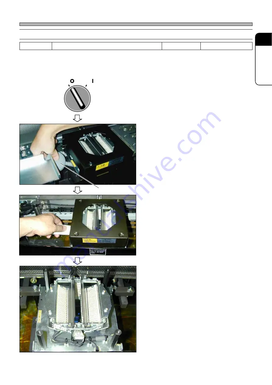
Page 120: ...h at full stroke and spreads the grease over whole area of it 15 Press X axis 16 Press UNLOCK Continuous moving The X axis repeats to go back and forth at full stroke and spreads the grease over whole of ball screw and linear bearing 17 Press Y axis 18 Press UNLOCK Continuous moving The Y axis repeats to go back and forth at full stroke and spreads the grease over whole of ball screw and linear be...

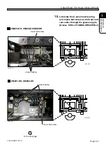
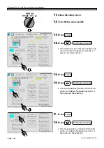
Page 121: ...low away the dust from between the illumination and the line camera by using the blower brush Blow away the dust from the left side or the front side Tools Blower brush Required time 5 minutes OFF ON SERVO 444C 490P Blower brush 444C E MMA01 A08 06 5 Wind a cloth around a stick or such a thin plate as a ruler and then wipe the lens face At this time removing the NG chip discharge box and its mount...

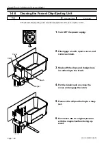
Page 122: ... and foreign bod ies adhering to the brush 4 Put the brush back on close the cover and engage the catch 5 Remove the chips adhering to a mag net 6 Put it back into its original position with the magnet surface facing up ward RELEASE TRIP O F F ON R E S E T 5 minutes Required time Tools The forced chip ejecting unit is standard equipment for DS but an option for DH Brush Catch Magnet Cover 444C 465...

Page 123: ...se Cover Only for DU DHU Specifications 1 Cleaning and lubricating the nozzle shaft support bearing 1 Ensure that the safety cover is closed and turn on the servo switch 2 Select the operation table 3 Press UNLOCK Head mainte posi The transfer head moves to the maintenance position 4 Turn OFF the power Lock the main switch A worker should carry the key DU DHU only 5 Open the cover at the lower rig...

Page 124: ...Make sure the exhaust sound disappears and the gauge shows 0 MPa Lock the valve lever A worker should carry the key DU DHU only 7 Open the safety cover 8 Lower the nozzle holder 9 Clean the bearing and groove by using a cotton bud To the next page 444C E MMA01 A08 03 Nozzle holder Groove Valve Bearing Cotton bud 444C 443P 444C 402P 444C 444P 1 2 3 4 1 2 3 ...

Page 125: ...ricating in steps 8 to 11 for all nozzles 2 Checking the vacuum pressure Ensure that the vacuum pressure is within the specified value Check it with the nozzle set to all heads 1 Supply the air Open the lever Adjust the air pressure within the specified value using the valve Lock the valve 2 Turn ON the power To the next page 444C E MMA01 A08 01 444C 402P 444C 445P RELEASE TRIP O F F ON R E S E T ...

Page 126: ...ent screen appears 4 Press Output check The Output Check screen appears 5 Select the operation table the one with the transfer head of which the vacuum pressure is measured 6 Press UNLOCK The display turns to be ON and the vacuum pump works 7 Press UNLOCK The display turns to be ON and the air flows into the pass To the next page 444C EEn Ma 001 444C EEn MaOc 015 ...

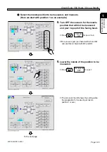
Page 127: ...or the nozzle position that will not be measured and pos1 to pos6 of the facing head Press UNLOCK for pos 2 to 6 One vacuum pump is shared with AF and AR and another is shared with BF and BR 9 Lower the nozzle of the position to be measured Press UNLOCK for pos 1 The screen at the left shows the setting when the preparation for measuring at nozzle position 1 is over To the next page Vacuum ON Nzl ...

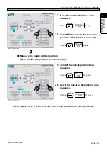
Page 128: ...h has been measured Press UNLOCK for pos 1 Measure the nozzle at other position Here we describe position 2 as an example 19 Turn ON the nozzle position to be measured Press UNLOCK for pos 2 20 Lower the nozzle at the position to be measured Press UNLOCK for pos 2 After it repeat steps 10 to 20 and check the vacuum pressure at all nozzle positions Vacuum OFF Vacuum ON Nzl Extend ON 2 1 1 2 Nzl Ext...

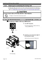
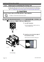
Page 129: ... Feeder Base Cover Only for DU DHU Specifications Procedures of CM201 D DU and CM202 D DU 1 Turn OFF the power Lock the main switch A worker should carry the key DU DHU only 2 Open the cover at the lower right of the machine rear side Remove the screw with the Philips driver M60E DO NOT TOUCH THE CUTTER BLADE WITH YOUR FINGERS The edge is so sharp that you may injure yourself CAUTION Tools Philips...

Page 130: ... Feeder Base Cover Only for DU DHU Specifications Procedures of CM201 D DU and CM202 D DU 1 Turn OFF the power Lock the main switch A worker should carry the key DU DHU only 2 Open the cover at the lower right of the machine rear side Remove the screw with the Philips driver M60E DO NOT TOUCH THE CUTTER BLADE WITH YOUR FINGERS The edge is so sharp that you may injure yourself CAUTION Tools Philips...

Page 131: ...il it stops Make sure the exhaust sound disappears and the gauge shows 0 MPa Lock the valve lever A worker should carry the key DU DHU only 4 Open the safety cover 5 Draw the tape feeder table 6 Remove the tape chute Loosen the bolt set to the inner side To the next page 444C E MMA01 A09 03 Bolt 444C 464P 444C 465P Tape chute 444C 425E Valve 444C 402P 1 2 3 4 1 2 3 ...

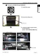
Page 132: ...chute After that carry out these steps in the reverse order to prepare for supplying the power Procedure of CM201 DH and CM202 DH DHU DK 1 Turn OFF the power 2 Open the safety cover 3 Lubricate through the grease nipple for the cutting unit Grease SHELL STAMINA GREASE RL2 444C 467P Fixed blade Movable blade 444C 426E Fulcrum part Fulcrum part RELEASE TRIP O F F ON R E S E T 444C 505P 444C 504P Gre...

Page 133: ...1 DS and CM202 DS 1 Turn OFF the power 2 Remove the cutting cover 3 Lubricate through the grease nipples for the cutting unit Grease SHELL STAMINA GREASE RL2 RELEASE TRIP O F F ON R E S E T E24C 402P E24C 403P E24C 405P E24C 404P E24C 406P Grease nipples Cutting cover Left Two locations Right One location ...

Page 134: ...achine adjust The Machine adjustment menu screen appears 2 Press Output check The Output check screen appears 3 Select the operation position the table with the transfer head of which the vacuum pressure is to be mea sured To the next page 444C E MMA01 A09 07 Tools Required time 5 minutes 444C EEn MaOc 015 ...

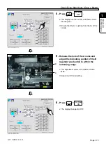
Page 135: ...o the pass Ensure that the air is jetting from the tip of the nozzle 5 Release the lock of the A valve and adjust the indicating pointer of the B regulator graduation to within the indicating range The adjustment value is 0 04 MPa 0 005 MPa Adjust it with the air jetting 6 Press UNLOCK The display changes to OFF Air blow OFF Air blow ON 444C 491P B A ...

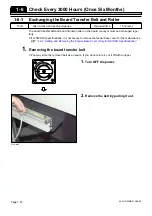
Page 136: ...sary to remove the feeder base cover for the maintenance 1 2 3 Setting and Removing the Feeder Base Cover Only for DU DHU Specifications 1 Removing the board transfer belt You may store the removed belt as an spare If you do not store it cut it off with a nipper 1 Turn OFF the power 2 Remove the belt by pulling it out 444C E MMA01 A09 04 Tools Allen wrench and push pull gauge Required time 15 minu...

Page 137: ...board transfer roller 3 Setting the board transfer belt 1 Check the transfer direction of the belt Fit the arrow direction printed on the belt to the transfer direction 2 Insert the belt into the gap between the roller and the guide 3 Put the belt to the driving pulley and the tension pulley 4 Check the belt tension For checking and adjusting the tension 1 4 5 Checking and Lubricating the Board Co...

Page 138: ...ons it is necessary to remove the feeder base cover for the maintenance 1 2 3 Setting and Removing the Feeder Base Cover Only for DU DHU Specifications 1 Press Machine adjust 2 Press Output check M60E DO NOT TOUCH THE CUTTER BLADE WITH YOUR FINGERS The edge is so sharp that you may injure yourself CAUTION Tools Philips driver and allen wrench Required time 30 minutes To the next page M106E BE SURE...

Page 139: ...parts is not closed it is impossible to operate No 64 should be OFF 5 Release the air pressure inside the machine Close the main air valve Pull up the regulator knob and turn it to the left until it stops Make sure the exhaust sound disappears and the gauge shows 0 MPa Lock the valve lever A worker should carry the key DU DHU only 4H4C 513P 444C EEn MaOc 015 To the next page 4 1 2 3 ...

Page 140: ...e the cover positioning bolt of the fixed blade and set the bolt for lifting See the below picture Bolt for lifting The bolt for lifting is attached to the jig for maintenance 9 Remove the fixing bolt by using the exclusive tool Exclusive tool RELEASE TRIP O F F ON R E S E T 444C 512P 4H4C 501P Fixed blade Movable blade Cover positioning bolt 4H4C 515P 4H4C 516P 4H4C 517P Chute To the next page 44...

Page 141: ...Remove the bolt for lifting from the fixed blade set it to the movable blade See the picture 1 on the left 12 Remove the fixing bolt by using the exclusive tool Take care not to drop the blade when removing the last bolt 13 Remove the movable blade holding the bolt for lifting 14 Set the blot for lifting to the new movable blade 15 Insert the movable blade holding the bolt for lifting 16 Set the f...

Page 142: ... for lifting 20 Set the bolt for lifting to the new fixed blade 21 Insert the fixed blade holding the bolt for lifting 22 Set the fixing bolt and tighten it lightly 23 Press the fixed blade against the frame on the inner side At this time take care not to touch the blade parts 24 Tighten the fixing bolt by using the exclusive tool 25 Remove the bolt for lifting and set the cover positioning bolt 2...

Page 143: ... the position so that the positioning bolt will fit to the 2 positioning holes of the chute See the picture 28 Set the 3 fixing bolt tighten it 29 Open the air valve 30 Operate the regulator set to the regu lated pressure 31 Turn ON the power And turn OFF ON the cutter on the screen of the output test and check the abnormal noise 4H4C 518P ...

Page 144: ... is required regularly 1 Turn OFF the power 2 Open the cover at the rear side of the machine AR BR Remove the setting bolt by using the philips driver 3 Remove the tubes black X 2 con nected to the vacuum pump 4 Remove the 2 bolts fixing the vacuum pump To the next page 444C E MMA01 A09 05 Tools Required time 60 minutes Philips driver allen wrench RELEASE TRIP O F F ON R E S E T 444C 492P 444C 493...

Page 145: ...ing order not to mistake The mistaken order will cause the reverse of the vacuum pump 5 Open the distributor 6 Remove the vacuum pump and re place it with a new one 7 Connect the tube 8 Connect the wiring as written down at step 5 9 Fix the vacuum pump by the 2 bolts 10 Set the cover Checking the vacuum pressure 1 5 1 Cleaning the Lubricating the Transfer Head 2 Checking the vacuum pressure 444C E...

Page 146: ...icator 3 color indicator 1 Turn OFF the power 2 Remove the upper bolt of the 3 color indicator by using the stepladder 3 Remove the cover in turn from upper and remove the inside bulb 4 Replace the bulb with a new one 5 Set the cover 2 Replacing the stage indicator 1 Turn OFF the power 2 Remove the cover of the indicator 3 Remove the inside bulb 4 Replace the bulb with a new one 5 Set the cover To...

Page 147: ...ement 1 7 5 Tape Feeder Base Replacing the Air Cylinder The air cylinder is an important parts that move the tape feeder accurately If the tape feed is not performed accurately the chips can be not fully sent and the miss of the picking will cause And so the regular replacement is required Please tell our service engineer in case of the parts replacement 1 7 6 Color Touch Panel Replacing the Back ...

Page 148: ...while picking and mounting If the control is not performed successfully the miss of the picking and mounting occurs So the regular replacement is required 1 Turn OFF the power 2 Remove the wiring of the valve con nected to the valve 3 Remove the valve Remove the 2 setting bolts by using the philips driver To the next page Tools Philips driver Required time 120 minutes RELEASE TRIP O F F ON R E S E...

Page 149: ... valve with a soft cloth soaked with alcohol 5 Align the packing with the bolt hole of the new valve and set it to the flange Fasten the bolt adding the power of 0 15 N m 6 Connect the wiring of the valve to a new one 7 Turn ON the power Checking the vacuum pressure 1 5 1 Cleaning the Lubricating the Transfer Head 2 Checking the vacuum pressure 444C 497P 444C 498P 444C 499P ...

Page 150: ... the bad motion of the cylinder and occurs the miss of the picking and mounting So regular replacement is required 1 Turn OFF the power 2 Release the main air 3 Remove the head cover Remove the screw setting the head cover by using the philips driver To the next page Tools Philips driver allen wrench Required time 30 minutes RELEASE TRIP O F F ON R E S E T 444C 436P 444C 437P Philips driver Head c...

Page 151: ...the setting position and wiring name The setting working will be smooth 5 Remove the pipe tube connected to the valve manifold Write down the setting position and order The setting work will be smooth 6 Remove the 2 bolt setting the bulb manifold 7 Replace it with a new valve and fix it by the valve To the next page 444C 500P 444C 501P 444C 502P ...

Page 152: ...Hours Once Two Years 8 Connect the pipe and wiring as be recorded 9 Set the head cover 10 Turn ON the power 11 Press Machine adjust The Machine adjustment menu screen appears 12 Press Return to origin Returning to origin is performed To the next page ...

Page 153: ...09 04 Check Every 560 Hours Once a Month 13 Press UNLOCK START 14 Press Output check Output check screen is displayed 15 Select the operation position the table with the transfer head of which the vacuum pressure is to be mea sured To the next page ...

Page 154: ...arting form the position1 Press UNLOCK in order from pos 1 and check the nozzle come out Nzl Extend OFF 1 8 3 Tape Feeder Base Replacing the Valve For Cylinder of the Tape Feeder If bad motion owing to the abrasion of the valve the motion of the tape feeder will not be accurate eventually pick up miss will occur Please tell our service engineer in case of the parts replacement ...

Page 155: ...le Holder Clamp Arm Spring for Clamp Claw Holder Spring for Nozzle Cushion Abrasion of each parts will cause an unsmooth nozzle motion That will be the major factor of pick up mount trouble So the parts need to be replaced regularly We recommend replacing each part simultaneously at the same timig 1 9 3 XY Unit Cable Bear Abrasion of the cable bear will cause the disconnection of the wiring and pi...

Page 156: ... Procedure 1 Turn OFF the power supply of the machine 2 Remove the screws at the side of the color touch panel cover and remove the cover M59EB CUT OFF THE POWER SUPPLY BEFORE CARRYING OUT ANY WORK FOR THE MACHINE You will have a serious electric shock WARNING To the next page 493C 025P Back light Color touch panel 444C 463E Screw Cover 444C E MMA01 A09 02 1 10 Replacing Consumable Parts ...

Page 157: ...ull out the back light 6 Insert the replacement back light 7 Connect the power supply connector 8 Restore the raised bending with a needle nose plier and the like 9 Attach the replacement back light 10 Attach the color touch panel cover 11 Turn ON the power supply of the machine Make sure the back light turns on One M3 countersunk screw Hatch Plate for back light replacement 493C 024P 493C 029P 1 ...

Page 158: ...Page 1 96 444C E MMA01 A09 00 MEMO ...

Reviews: