


ACC
BATTERY 15A
(
✽
)
(
✽
)
ACC
BATTERY 15A
ACC
BATTERY 15A
L
R
(
✽
)
(
✽
)
(
✽
)
(
✽
)
ISO Antenna Adapter
(
If needed
)
ISO-Antennenadapter
(falls erfor derlich)
Adaptateur d'antenne ISO
(si nécessaire)
ISO antenne-adapter
(Indien nodig)
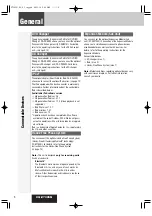
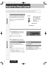
Wiring/Verdrahtung/Câblage/Bedrading
Caution
To prevent damage to the unit, do not connect the power connector until the whole
wiring is completed.
Vorsicht
Um Beschädigungen des Gerätes zu vermeiden, schließen Sie den Versorgungsstecker
erst an, nachdem die gesamte Verdrahtung vollständig beendet wurde.
Attention
Ne pas introduire la prise d'alimentation secteur dans l'appareil tant que le câblage n'est
pas complètement terminé afin de ne pas risquer d'endommager l'appareil.
Let op
Om schade aan het toestel te voorkomen mag u de stroomstekker pas aansluiten
wanneer de bedrading volledig is aangesloten.
ACC
BATTERY 15A
A
C1 :
External Mute Lead
To the Navi Mute lead of the Panasonic car navigation system
or car telephone mute lead.
Externes-Stummschaltungskabel
An das Navigationssystem-Stummschaltungskabel des
Panasonic Navigationssystems oder an das
Autotelefon-Stummschaltungskabel.
Fil de Mise en sourdine extérieure
A raccorder au fil Navi Mute du système de navigation automobile de
Panasonic ou au fil de mise en sourdine du téléphone pour véhicule.
Externe-geluiddempingsdraad
Naar de Navi Mute draad van een Panasonic auto-navigatiesysteem
of naar de dempingsdraad voor deautotelefoon.
B
C3 :
ISO Connector
A
ISO-Stecker
A
Connecteur ISO
A
ISO aansluiting
A
A7 :
Power Lead
(
ACC or IGN
)
To ACC power, +12 V DC.
Versorgungskabel
(ACC oder IGN)
An die ACC-Stromklemme, +12 V Gleichspannung.
Fil d’alimentation
(ACC ou IGN) A l’alimentation ACC, +12 V CC.
Stroomdraad
(ACC of IGN) Naar ACC stroomvoorziening, + 12 V gelijkstroom.
A8 :
Ground Lead
To a clean, bare metallic part of the car chassis.
Massekabel
An ein sauberes, metallisches Teil des Fahrzeugchassis.
Fil de mise à la masse
A une partie métallique propre découverte du châssis de voiture.
Aarding
Naar een schoon, bloot metalen onderdeel van het chassis.
A4 :
Battery Lead
To the car battery, cont12 V DC.
Batteriekabel
An die Batterie des Fahrzeuges, kontinui12 V Gleichspannung.
Fil de batterie
A la batterie de voiture, alimentation continue de +12 V CC.
Accudraad
Naar de accu van de auto, doorlopende stroomvoorz 12 V gelijkstroom.
A5 :
A
A5
(Orange)/(Orange)/(Orange)/(Oranje)
(Red)/(Rot)/(Rouge)/(Rood)
(Black)/(Schwarz)
/
(Noir)/(Zwart)
(Yellow)/(Gelb)
/
(Jaune)
/
(Geel)
Motor Antenna Relay Control Lead
To Motor Antenna. (Max. 100 mA) (This lead is not
intended for use with a switch actuated power antenna)
Steuerkabel für Relais der motorbetriebenen Antenne
Zur motorbetriebenen Antenne
(max. 100 mA) (Dieses Kabel dient nicht für die Verwendung mit einer über einen
Schalter aktivierten motorbetriebenen Antenne.)
Fil de commande de relais d’antenne motorisée
A l’antenne motorisée (100 mA maxi.)
(Ce fil n’est pas conçu pour l’usage avec l’antenne commandée par interrupteur.)
Stuurdraad relais gemotoriseerde antenne
Naar de gemotoriseerde antenne. (Max. 100
mA) (Deze draad is niet bedoeld voor een gemotoriseerde antenne die met een
schakelaar wordt ingeschakeld.)
(Blue)/(Blau)/(Bleu)/(Blauw)
+
B7
-
B8
+
B1
-
B2
+
B3
-
B4
+
B5
-
B6
B7 :
Rear Left + (Green)
Hinten Links + (Grün)
Arrière (Vert)
Links (Groen)
B5 :
Front Left + (White)
Vorne Links + (Weiß)
Avant (Blanc)
Links voor + (Wit)
B3 :
Front Right + (Gray)
Vorne (Grau)
Avant droit + (Gris)
Rechts voor + (Grijs)
B1 :
Rear Right + (Violet)
Hinten (Violett)
Arrière droit + (Violet)
Rechts (Paars)
B2 :
Rear Right – (Violet w/black stripe)
Hinten Rechts – (Violett mit schwarzem Streifen)
Arrière droit – (Violet à rayures noires)
Rechts achter – (Paars met zwarte streep)
B4 :
Front Right – (Gray w/black stripe)
Vorne Rechts – (Grau mit schwarzem Streifen)
Avant droit – (Gris à rayures noires)
Rechts voor – (Grijs met zwarte streep)
B6 :
Front Left – (White w/black stripe)
Vorne Links – (Weiß mit schwarzem Streifen)
Avant gauche – (Blanc à rayures noires)
Links voor – (Wit met zwarte streep)
+
-
ISO Connector
ISO-Stecker
Connecteur ISO
ISO aansluiting
B
B
B
B
B8 :
Rear Left – (Green w/black stripe)
Hinten Links – (Grün mit schwarzem Streifen)
Arrière gauche – (Vert à rayures noires)
Links achter – (Groen met zwarte streep)
B
CX-DP880N
CQ-C7305N
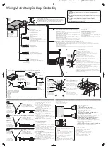
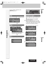
System Upgrade Example: Connecting with the CD changer/Beispiel für eine System-Erweiterung: Anschluss an den CD-Wechsler
/Exemple de mise à niveau de système: Raccordement à un changeur de disque CD/Voorbeeld systeemuitbreiding: Aansluiten van een CD-wisselaar
CA-CC30N
CHANGER IN
(Optional)
(Option)
(en option)
(Optioneel)
(Optional)
(Option)
(en option)
(Optioneel)
(
L
)/(
L
)/(G)/(L)
(White)/(Weiß)/(Blanc)/(Wit)
(
R
)/(
R
)/(D)/(
R
)
(Red)/(Rot)/(Rouge)/(Rood)
DIN Cord
DIN-Kabel
Cordon DIN
DIN snoer
RCA Cord
Cinchkabel
Cordon RCA
RCA (tulpstekker) snoer
Ground Lead
Massekabel
Fil de mise à la masse
Aarding
Battery Lead
Batteriekabel
Fil de batterie
Accudraad
Conversion Cable for DVD/CD Changer
Umwandlungskabel für DVD/CD-Wechsler
Câble de conversion de changeur DVD/CD
Conversiekabel voor DVD/CD-wisselaar
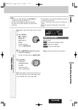
●
The pin arrangement of the power connector
conforms to ISO standard.
●
Please check that the pin arrangement of the
connector in your car conforms to ISO standard.
●
For car types A and B, change the wiring of the
red and yellow leads as shown at below.
●
After connection, insulate the portions marked (
✽
)
with insulating tape.
Note:
For cars other than types A and B, please
consult your local car shop.
Precautions
(
ISO Connector
)
●
Die Stiftbelegung des Versorgungssteckers entspricht
dem ISO-Standard.
●
Bitte stellen Sie sicher, dass die Stiftbelegung
des Steckers in Ihrem Fahrzeug dem ISO-Standard
entspricht.
●
Für Fahrzeuge der Typen A und B, ändern Sie die
Verdrahtung der roten und gelben Leiter gemäß Abbildung.
●
Nach dem Anschluss isolieren Sie die mit (
✽
) markierten
Abschnitte mit Isolierband.
Hinweis:
Für andere Fahrzeuge als Typ A und B,
wenden Sie sich bitte an eine örtliche Pkw-Werkstatt.
Vorsichtsmaßregeln (ISO-Stecker)
●
La disposition des broches du connecteur d'alimentation
est conforme à la norme ISO.
●
Veuillez vérifier si que la disposition des broches du
connecteur d'alimentation dans votre voiture est conforme
à la norme ISO.
●
Pour les types de voiture A et B, changer le câblage des
fils rouge et jaune comme indiqué ci-dessous.
●
Après avoir fait les connexions, isoler les sections
marquées (
✽
) avec de la bande isolante.
Remarque:
Pour les voitures autres que des types A et B,
veuillez consulter votre magasin de matériel automobile local.
Précautions (Connecteur ISO)
●
De pen-configuratie van de stroomstekker voldoet aan de
ISO standaard.
●
Controleer of de pen-configuratie van de stekker in uw
auto eveneens voldoet aan de ISO standaard.
●
Voor auto's van type A en B, dient u de bedrading voor de rode
en gele draden te wijzigen zoals hieronder staat aangegeven.
●
Na het aansluiten dient u de gedeelten die met (
✽
)
gemarkeerd zijn met isolatieband af te plakken.
Opmerking:
Voor andere auto's dan die van type A en B
dient u uw garage te raadplegen.
Voorzorgen (ISO stekker)
Standard ISO/ISO-Standard/Normes ISO/Standaard ISO
IGN or ACC 12 V supply
12 V-Versorgung
(IGN/ACC)
Alimentation 12 V en
IGN ou ACC
IGN of ACC 12 V
stroomvoorziening
Car-side connector
Steckverbinder am Fahrzeug
Connecteur côté voiture
Stekker aan autozijde
Car-side connector
Steckverbinder am Fahrzeug
Connecteur côté voiture
Stekker aan autozijde
Car-side connector
Steckverbinder am Fahrzeug
Connecteur côté voiture
Stekker aan autozijde
12 V Batteries (Continuous supply)
12 V-Batterie (Dauerversorgung)
Batterie de 12 V (alimentation continue)
12 V accu (doorlopende stroomvoorziening)
Car Type A/Kraftfahrzeug des Typs A/Type de voiture A/Autotype A
Car Type B/Kraftfahrzeug des Typs B/Type de voiture B/Autotype B
A7
A4
IGN or ACC 12 V supply
12 V-Versorgung
(IGN/ACC)
Alimentation 12 V en
IGN ou ACC
IGN of ACC 12 V
stroomvoorziening
A4
12 V Batteries (Continuous supply)
12 V-Batterie (Dauerversorgung)
Batterie de 12 V (alimentation continue)
12 V accu (doorlopende stroomvoorziening)
A7
No connection
Kein Anschluss
Aucune connexion
Geen aansluiting
A4
12 V Batteries (Continuous supply)
12 V-Batterie (Dauerversorgung)
Batterie de 12 V (alimentation continue)
12 V accu (doorlopende stroomvoorziening)
A7
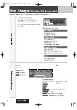
Power connector/Versorgungsstecker/Connecteur d’alimentation/Stroomstekker
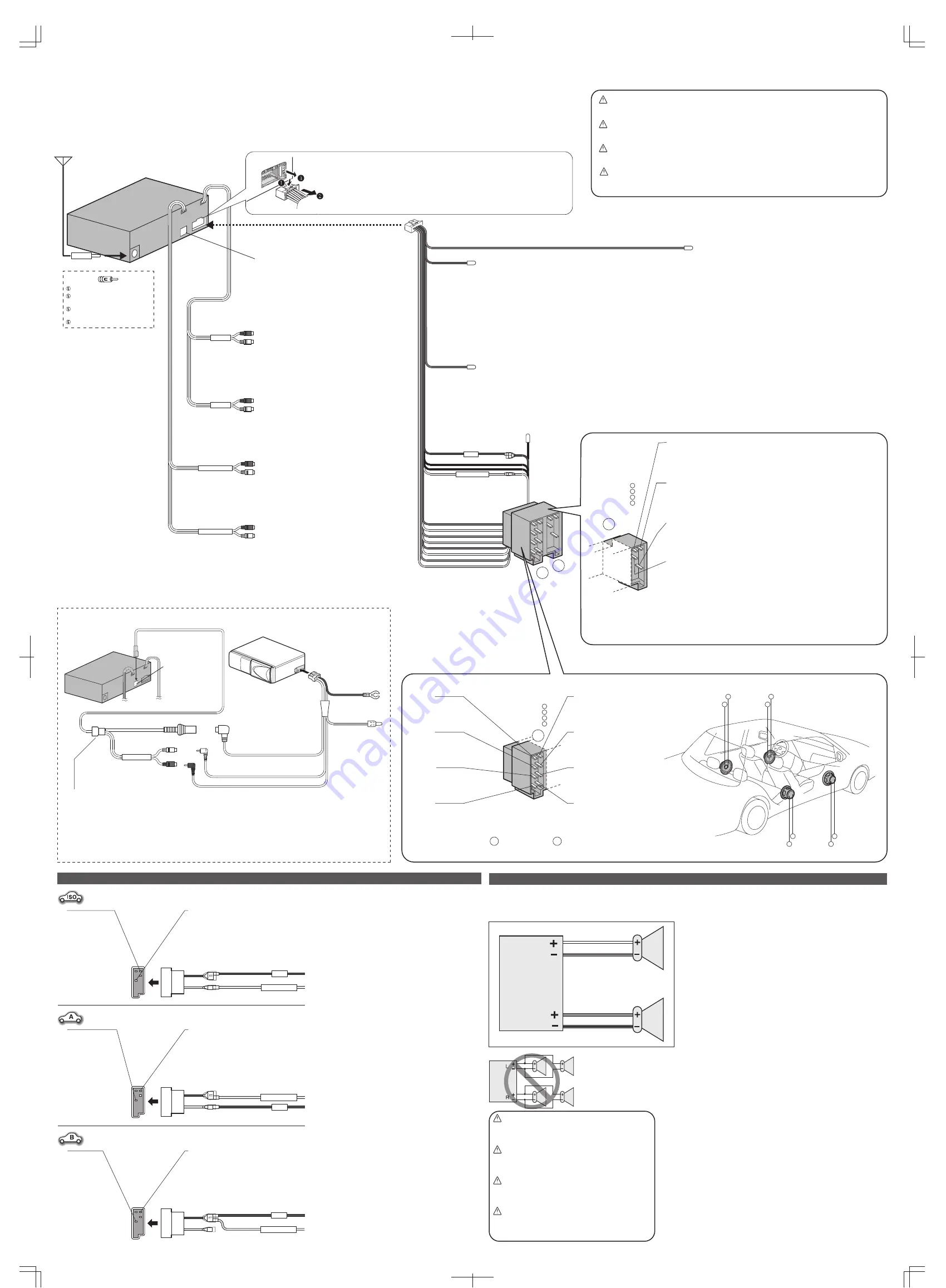
Connect as follows.
Nehmen Sie den Anschluss wie folgt vor.
Branchez les haut-parleurs comme suit.
Sluit de luidsprekers als volgt aan.
Speaker Connection/Anschluss der Lautsprecher/Branchement avec les haut-parleurs/Aansluiten van de luidsprekers
●
Do not use a 3-wire type speaker system
having a common earth lead.
●
Verwenden Sie niemals Lautsprechersysteme mit
Dreierverkabelung, die einen gemeinsamen
Erdungsleiter aufweist.
●
Ne pas utiliser pas de système de haut-parleur
de type à 3 fils ayant un fil de mise à la masse
commun.
●
Gebruik geen luidsprekersysteem met drie
draden en een gedeelde aarddraad.
Caution
●
Do not connect more than one speaker to one set of
speaker leads. (except for connecting to
a tweeter)
Vorsicht
●
Schließen Sie niemals mehr als einen Lautsprecher
an einen Satz Lautsprecherleiter an. (außer bei
Anschluss eines Hochtonlautsprechers)
Attention
●
Ne raccorder pas plus d'un haut-parleur à un
ensemble de fils de haut-parleur. (Sauf lors du
raccordement à un tweeter)
Let op
●
Sluit niet meer dan één luidspreker aan op één paar
luidsprekerdraden. (Behalve bij aansluiting op een
tweeter.)
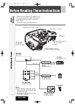
Antenna
Antenne
Antenne
Antenne
PRE-OUT REAR
PRE-OUT FRONT
AUX1-IN
S.W-OUT
(Brown w/black stripe)/(Braun mit schwarzem Streifen)/(Brun à rayures noires)/
(Bruin met zwarte streep)
External Remote Control Lead
When using a non-Panasonic external remote control, refer to the manufacture for their
product before connecting.
Leitungsdraht für externe Fernbedienung
Wenn Sie eine externe Fernbedienung verwenden, die nicht von Panasonic hergestellt
wurde, wenden Sie sich vor dem Anschluss an den Hersteller des Produktes.
Fil de la télécommande extérieure
En cas d’utilisation d’une télécommande extérieure non-Panasonic, se référer aux
conseils du fabricant concerné pour les connexions électriques.
Externe afstandsbedieningsdraad
Bij gebruik van een externe afstandsbediening die niet van Panasonic is, dient u voor
aansluiting de handleiding of de fabrikant van het product in kwestie te raadplegen.
Fuse (15 A)
Refer fuse replacement to your nearest authorized Panasonic Service Centre. Do
not try fuse replacement by yourself.
Sicherung (15 A)
Wenden Sie sich zum Austausch der Sicherung an eine autorisierte Panasonic-
Kundendienststelle in Ihrer Nähe. Versuchen Sie nicht, den Austausch selbst vorzunehmen.
Fusible (15 A)
Confier le remplacement de fusible au centre de service de service après-vente
Panasonic agréé le plus proche. Ne pas essayer de remplacer le fusible tout(e) seul(e).
Zekering (15 A)
Laat het vervangen van de zekering over aan uw dichtstbijzijnde Panasonic
service-centrum. Probeer in geen geval zelf de zekering te vervangen.
System-up Connector
Stecker für Systemerweiterung
Connecteur de mise à niveau de système
Systeemuitbreidingsaansluiting
(
R
)/(
R
)/(D)/(
R
)
(Red)/(Rot)/(Rouge)/(Rood)
(
L
)/(
L
)/(G)/(L)
(White)/(Weiß)/(Blanc)/(Wit)
(
R
)/(
R
)/(D)/(
R
)
(Red)/(Rot)/(Rouge)/(Rood)
(
L
)/(
L
)/(G)/(L)
(White)/(Weiß)/(Blanc)/(Wit)
(
R
)/(
R
)/(D)/(
R
)
(Red)/(Rot)/(Rouge)/(Rood)
(
L
)/(
L
)/(G)/(L)
(White)/(Weiß)/(Blanc)/(Wit)
(
R
)/(
R
)/(D)/(
R
)
(Red)/(Rot)/(Rouge)/(Rood)
(
L
)/(
L
)/(G)/(L)
(White)/(Weiß)/(Blanc)/(Wit)
Preamp Out Connector
(
Rear
)
Vorverstärker-Ausgang
(Hinten)
Connecteur de sortie de préamplificateur
(arrière)
Uitgangsaansluiting voorversterker
(achter)
AUX Input Connector
AUX-Eingangsstecker
Connecteur d'entrée AUX
AUX-ingangsaansluiting
Preamp Out Connector
(
Front
)
Vorverstärker-Ausgang
(Vorne)
Connecteur de sortie de préamplificateur
(avant)
Uitgangsaansluiting voorversterker
(voor)
System-up Connector
Stecker für
Systemerweiterung
Connecteur de mise à
niveau de système
Systeemuitbreidingsaa
nsluiting
Subwoofer Output Connector
The RCA cord of an external power amplifier should be
connected.
Subwoofer-Ausgangsstecker
Hier das RCA-Kabel eines externen Leistungsverstärkers
anschließen.
Connecteur de sortie des extrêmes-graves.
Le cordon RCA d’un amplificateur de puissance extérieur
doit être raccordé.
Subwoofer uitgangsaansluiting
Hierop kunt u via een RCA (tulpstekker) snoer een externe
eindversterker aansluiten.
●
Use ungrounded speakers only.
Allowable input : 50 W or more
Impedance : 4 – 8
Ω
●
Use of speakers which do not match the specifications can cause
burning, smoking or damage of the speakers.
●
Distance between speaker and amplifier: 30 cm or more
●
Verwenden Sie nicht geerdete Lautsprecher.
Zulässige Belastbarkeit: 50 W oder mehr
Impedanz : 4 – 8
Ω
●
Die Verwendung von Lautsprechern, die den technischen Daten
nicht entsprechen, kann zu Brand, Raucherntwicklung oder
Beschädigung der Lautsprecher führen.
●
Entfernung zwischen Lautsprecher und Verstärker: 30 cm oder mehr
●
Utilisez uniquement des haut-parleurs non reliés à la masse.
Puissance d'entrée admissible: 50 W ou davantage
Impédance: 4 – 8
Ω
●
L’utilisation de haut-parleurs non appariés aux spécifications
peuvent engendrer une inflammation, de la fumée voire
endommager les haut-parleurs.
●
Distance entre le haut-parleur et l'amplificateur: 30 cm ou davantage
●
Gebruik uitsluitend ongeaarde luidsprekers.
Toegestaan ingangsvermogen: 50 W of hoger
Impedantie: 4 – 8
Ω
●
Gebruik van luidsprekers die niet voldoen aan de specificaties kan
leiden tot brand, rookvorming of beschadiging van de luidsprekers.
●
Afstand tussen luidspreker en versterker: 30 cm of meer
C4 :
(Blue w/white stripe)/(Blau mit weißem Streifen)/(Bleu à rayures blanches)/(Blauw met witte streep)
Amp·Relay Control Power Lead
To Panasonic power amplifier. (Max. 100 mA) (synchronized with the power on/off of amplifier)
Stromversorgungskabel für Verstärkerrelaissteuerung
an den Panasonic Leistungsverstärker. (Max. 100 mA) (synchronisiert mit dem Ein/Ausschalten der
Stromversorgung des Verstärkers)
Fil d'alimentation de commande de relais d'amplificateur
à amplificateur de puissance Panasonic. (Max. 100 mA) (synchronisé à l'application ou la coupure
d'alimentation de l'amplificateur)
Versterker-relais Stuurstroomdraad
naar Panasonic eindversterker. (Max. 100 mA) (gesynchroniseerd met de eindversterker aan/uit)
CQ-C7305N Installation Instructions
(1-2)
YFM294C094CA


