Power
Amplifier
Center Speaker
Subwoofer
Power
Amplifier
2
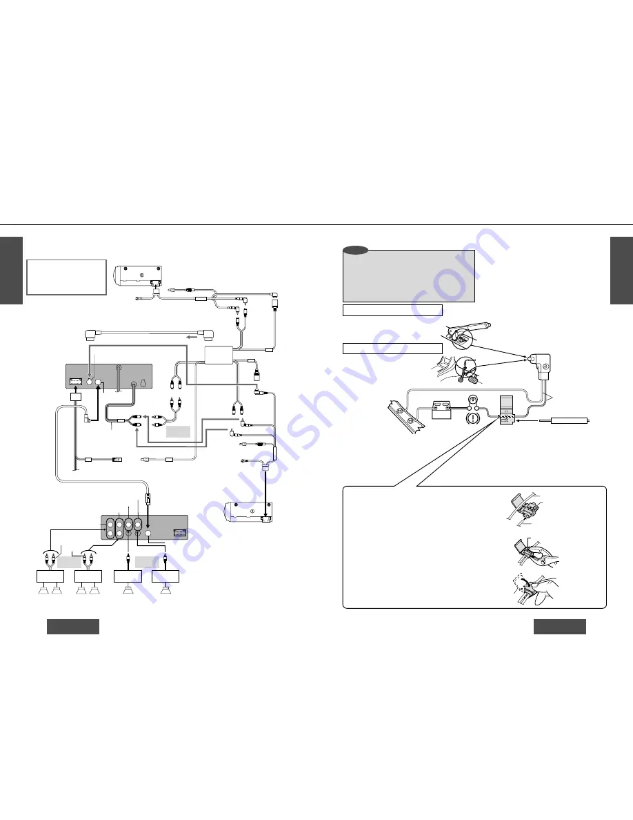
Power Amplifier Unit
(TWIN CD
•
C-CONT)
CX-DP88U
CA-CD55
CQ-DVR7000U
CX-DP88U
Ground Lead
Be sure to connect to a well
grounded metallic part of your
car because noises or troubles
may occur.
Battery Lead
Battery Lead
Ground Lead
Yellow
(Supplied to CA-CD55)
White (L)
White (L)
White (L)
(If only 1 Changer is used, connect as indicated by .)
Stereo Power
Amplifier
Upgraded System
Speakers
Upgraded System
Speakers
Stereo Power
Amplifier
Brown/White Stripe
:
Power Connector
White (L)
Red (R)
Red (R)
Red (R)
Red (R)
DIN Connector
DIN
Connector
DIN Extension Cord
Dual Changer
Output Cord
Changer Connector
Changer 1
Connecting
Cord
Changer 2
Connecting
Cord
Fuse (3 A)
Yellow
Fuse (3 A)
(CD.C-1)
(CD.C-2)
(CH
•
C-IN)
(TWIN CD
•
C-CONT)
RCA Cord
(Option)
Dual Changer Control Cord
>
12 pin audio connector
Pre-out (Front)
Pre-out (Rear)
Pre-out (Center)
Pre-out (Subwoofer)
RCA Cord
(Option)
RCA Cord
(Option)
Amplifier Unit
Connector
Control Unit Connector
R
R
L
L
L
L
L : White
R : Red
White (L)
Red (R)
White (L)
Red (R)
Changer Input Cord
Example Combination
≥
CD changer (CX-DP88U)
≥
Stereo power amplifier
≥
Upgraded system speakers
PARKING BRAKE
Parking Brake Switch
Cords connected to
the vehicle
Parking Brake Cord
Brake Lamp
Battery
Chassis
?
Clamp Connector
Blue/Yellow Stripe
Hand-operated parking brake
Foot-operated parking brake
E
N
G
L
I
S
H
53
E
N
G
L
I
S
H
54
CQ-DVR7000U
CQ-DVR7000U
72
73
Wiring Connections (continued)
Vehicle Cord
Parking Brake Cord
Element
Cover
Push the end of the cord
in until it touches this part.
Of the 2 cords emerging from the parking
brake switch, connect the player’s parking
brake cord to the one that is not connected to
the vehicle’s chassis while the brake is in the
released state.
Connecting the clamp connector
?
≥
Attach the clamp connector to the vehicle cord at a suitable
position.
≥
Note that if the cord being clamped onto is too thin
(0.3 mm
2
or less), the connection may not be adequate.
1
Push the end of the side brake cord into the hole on the
clamp connector.
Place the vehicle cord into the groove in the clamp
connector.
2
While making sure that the cords do not slip out of the
clamp connector, press the element down with a pair of
pliers.
3
Close the cover until it snaps shut.
≥
For safety’s sake, and to prevent accidents, the
parking brake cord must be connected.
≥
The parking brake connection should be
connected by a professional installer, if
possible. In case of difficulty, please consult
your nearest authorized Panasonic Servicenter.
Note:
≥
The position of the parking brake switch
depends on the car. (The figure shows
examples of where the switch might be
located.) For details on the exact location of
the parking brake switch in your car, contact
your dealer.
❐
Wiring diagram:
❐
Parking Brake Cord
Advanced system configuration
Caution
≥
This unit can be connected to an optional CD changer
(CX-DP88U). For details consult your nearest Panasonic dealer.
≥
For connection to the CD changer, refer to the operating
instructions of the CD changer (CX-DP88U).
Set the gain of the external amplifier to
the medium, and adjust the volume
level using the unit's volume control.


