background image

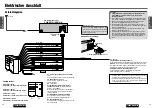
Antenna

e

Power

   Connector

CD Receiver

CQ-RDP151/RDP101N

(Yellow)

(Red)

ACC

(Black)

(White)

(Gray)

(Green)

Speaker 
Lead

(Violet)

(Dark blue)

(Dark blue)

A5

BATTERY

15 A

(Violet w/black stripe)

(Gray w/black stripe)

(White w/black stripe)

(Green w/black stripe)

A

A

B

B

* Telephone Mute

The sound from the speakers cannot be heard while the tele-
phone conversation is in progress.

** Navi Mute

The sound from the speakers cannot be heard while the naviga-
tion guide is on.

Cautions:

¡

Check the connectors provided on your car (see note on page
4 and 5) before connecting the system.

¡

This unit is designed for use in a car having a 12-volt negative
ground battery system.

¡

To prevent damage to the unit, be sure to follow the connection
diagram below.

¡

Strip about 5 mm of the lead ends for connection (only non-
ISO connector cords).

¡

Do not insert the power connector into the unit until the wiring
is completed.

¡

Be sure to insulate any exposed wires to prevent short circuit-
ing with the car chassis.  Bundle all cables, and prevent cable
terminals from touching any metal parts.

C1

: (Orange)

Telephone Mute Lead (*)

Connect to the car telephone mute lead.

Note:

The telephone mute lead is only for connection to the radio

mute lead.  Output other than telephone will not be muted

Navi Mute Lead (**)

To the Navi Mute lead of the Panasonic car navigation system.

A7 : Power Lead (ACC or IGN)

(Red)

To ACC power, +12VDC

A8 : Ground Lead

(Black)

To a clean, bare metallic part of the car
chassis

A5 :

(Dark blue)

Motor Antenna Relay Control Lead

(To Motor Antenna) (Max. 500mA)
This lead is not intended for use with a
switch actuated power antenna.

Amp·Relay Control Power Lead

This lead is for connection to a Panasonic
power amplifier.

A4 : Battery Lead

(Yellow)

To the car battery, cont12 V DC

(Orange)

Fuse (15 A)

20

21

CQ-RDP151/RDP101N

CQ-RDP151/RDP101N

15

E
N

G

L

I

S
H

16

E
N

G

L

I

S
H

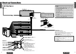
Cable Wiring Diagram

Electrical Connections

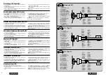
Speakers

Rear Left + (Green)
Rear Left – (Green w/black stripe)

Front Left + (White)
Front Left – (White w/black stripe)

Front Right + (Gray)
Front Right – (Gray w/black stripe)

Rear Right + (Violet)
Rear Right – (Violet w/black stripe)

1

2

To remove the Fuse

Fuse

e

Power Connector

If the fuse (rear panel) blows frequently, they
may be something wrong with the unit.
Consult your nearest Panasonic Service
Center for service.

Summary of Contents for CQ-RDP101N

Page 1: ...before using this product and save this manual for future use Bitte lesen Sie diese Bedienungsanleitung vor der Verwendung dieses Produktes aufmerksam durch und bewahren Sie sie danach für spätere Nachschlagzwecke sorgfältig auf Prière de lire ces instructions attentivement avant d utiliser le produit et garder ce manuel pour l utilisation ultérieure Leest u deze instructie alstublieft zorgvuldig ...

Page 2: ...e 70 Anti diefstal systeem 73 Elektrische aansluitingen 74 Aansluitingen luidsprekers 76 Zekering 76 Onderhoud 76 Technische gegevens 77 RDS mottagning datastyrd radiomottagning 82 Tidsinställning 85 CD spelare 86 Montering 88 Stöldskyddsanordning 91 Elektriska anslutningar 92 Anslutning av högtalare 94 Säkring 94 Underhåll 94 Tekniska data 95 Ricezione RDS Radio Data System 100 Regolazione dell o...

Page 3: ...ormes ISO La disposition des broches des connecteurs ISO de certaines voitures risque d être différente par rapport aux normes ISO Vérifier si la disposition des broches du connecteur de votre voiture est conforme aux normes ISO En ce qui concerne les véhicules des types A et B modifier le câblage des fils rouge et jaune comme indiqué ci contre Une fois le branchement réalisé isoler les sections i...

Page 4: ...ht the temperature inside the car may become very high It is advisable to drive the car and give the interior a chance to cool down before switching the unit on Power Supply This Product is designed to be used in a car having a 12 Volt negative ground battery system Disc Mechanism Do not insert coins or any small objects Keep screwdrivers and other metallic objects away from the disc mechanism and...

Page 5: ...ge 8 Caution To ensure safety never attempt to preset stations while you are driving r Mono Local Selection MONO LOCAL MONO Monaural reception Select MONO to reduce noise when receiving a stereo broadcast LOCAL Tunes in strong stations only FM broadcasts Press and hold PTY MONO LOCAL to change the mode Release when at the desired point AM broadcast Press PTY MONO LOCAL to switch LOCAL mode on and ...

Page 6: ...uency When reception is poor an RDS sta tion broadcasting the same program is tuned in automatically Display Change Press DISP to change the display as follows Auto Preset Memory Auto preset memory works only for RDS stations when AF mode is on Best Station Research Best Station Research is automatically activated to store the station with the best reception for each preset button PI Program Ident...

Page 7: ...P end Note Hold TUNE or TUNE to change numbers rapidly CT 10 35 CT 10 35 CT 10 00 CT 10 00 CT 0 00 NO CT AM 1305 RDS Radio Data System continued PTY Reception Program Type RDS FM stations provide a program type identification signal Example news rock classical music etc PTY Mode Press PTY to switch PTY display mode on or off When there is no corresponding program type NO PTY is display PTY RDS STE...

Page 8: ... loading a disc If the disc indicator is on eject the disc Stop and Disc Eject Press u to stop CD play and eject the disc Track Selection fTRACK Advance to the next track aTRACK Back to beginning of the current track Back to previous track Press twice Track Search Press and hold fTRACK Fast forward aTRACK Fast backward Release to resume the regular CD play CD Player 14 15 CQ RDP151 RDP101N CQ RDP1...

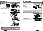
Page 9: ... 12 E N G L I S H Before installation check the radio operation with antenna and speakers Disconnect the cable from the negative battery terminal see caution below Unit should be installed in a horizontal position with the front end up at a convenient angle but not more than 30 Dashboard Installation Installation Opening The unit can be installed in any dashboard having an opening as shown at righ...

Page 10: ...e face plate while driving your car Do not place the face plate on the dashboard or nearby areas where the temperature rises to high levels 18 19 CQ RDP151 RDP101N CQ RDP151 RDP101N 13 E N G L I S H 14 E N G L I S H To Remove the Unit q Remove the removable face plate a Press the release button b Pull on the right side of the unit w Remove the trim plate t with a screwdriver e Pull out the unit wh...

Page 11: ...metal parts C1 Orange Telephone Mute Lead Connect to the car telephone mute lead Note The telephone mute lead is only for connection to the radio mute lead Output other than telephone will not be muted Navi Mute Lead To the Navi Mute lead of the Panasonic car navigation system A7 Power Lead ACC or IGN Red To ACC power 12VDC A8 Ground Lead Black To a clean bare metallic part of the car chassis A5 D...

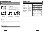
Page 12: ... separately using parallel vinyl insulated cords The speaker cords and the power amplifier unit should be kept away about 30 cm apart from the antenna and antenna extension cord Never connect the speaker cord to the body of the car Do not use a 3 wire type speaker system having a common earth lead Do not connect more than one speaker to one set of speaker leads MW Radio LW Radio CD Player FM Stere...

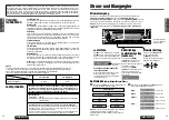
Page 13: ... sehr hoch an Fahren Sie daher Ihr Fahrzeug für einige Zeit mit geöffneten Fenstern damit sich das Innere abkühlen kann bevor Sie dieses Produkt einschalten Stromversorgung Dieses Produkt ist für die Verwendung in Kraftfahrzeugen mit 12 V Batterie und negativer Klemme an Masse ausgelegt CD Laufwerk Führen Sie niemals Münzen oder andere kleine Gegenstände ein Halten Sie Schraubendreher und andere m...

Page 14: ...e niemals eine Einstellung des Festsenderspeichers während der Fahrt versuchen r Umschalten zwischen Mono Ortsempfang MONO LOCAL MONO Monoempfang Wählen Sie MONO um die Rauschstörungen bei UKW Stereoempfang zu vermindern LOCAL Dient nur für die Abstimmung auf starke Ortssender UKW Empfang FM Betätigen und halten Sie die PTY MONO LOCAL Taste gedrückt um den Betriebsmodus umzuschalten Geben Sie dies...

Page 15: ...matisch die Uhrzeit und das Datum ein NO CT wird in Gebieten angezeigt in welchen der CT Service nicht zur Verfügung steht a Seite 31 für Einstellung der Uhrzeit AF Alternative Frequenz Wenn sich die Empfangsbedingungen verschlechtern wird automatisch auf einen RDS Sender mit dem gleichen Programm umgeschaltet Umschalten des Displays Drücken Sie die DISP Taste um das Display wie folgt umzuschalten...

Page 16: ... Drücken Sie die DISP Taste Ende Hinweis Halten Sie die TUNE oder TUNE Taste gedrückt um die angezeigten Zahlen schnell zu verstellen CT 10 35 CT 10 35 CT 10 00 CT 10 00 CT 0 00 NO CT AM 1305 Radio Daten System RDS Empfang Fortsetzung PTY Empfang Programmtyp Die RDS UKW Sender strahlen ein Signal zur Identifikation des Programmtyps aus Beispiel Nachrichten Rock klassische Musik usw PTY Modus Drück...

Page 17: ...altet ist bevor Sie eine Disk einsetzen Falls die Diskanzeige eingeschaltet ist werfen Sie die Disk aus Stoppen und Auswerfen der Disc Drücken Sie die u Taste um die Wiedergabe der Disc zu stoppen und werfen Sie die Disc aus Titelwahl fTRACK Taste Vorlauf zum Beginn des nächsten Titels aTRACK Taste Rücklauf zum Beginn des gegenwärtigen Titels Oder Rücklauf zum Beginn eines vorhergehenden Titels Ti...

Page 18: ... RDP101N 11 D E U T S C H 12 D E U T S C H Vor dem Einbau des Gerätes probieren Sie den Radiobetrieb mit Antenne und Lautsprechern aus Klemmen Sie das Massekabel vom Minuspol der Batterie ab siehe nachfolgende Vorsicht Sie sollten das Gerät in horizontaler Position einbauen wobei die Vorderseite für optimale Bedienung bis zu einem Winkel von 30 angehoben werden darf Einbau in das Armaturenbrett Ei...

Page 19: ...als das abnehmbare Bedienteil während der Fahrt Legen Sie das abnehmbare Bedienteil niemals auf das Armaturenbrett oder an einen ähnlichen Ort an dem die Temperatur stark ansteigen kann 36 37 CQ RDP151 RDP101N CQ RDP151 RDP101N 13 D E U T S C H 14 D E U T S C H Entfernen des Gerätes q Nehmen Sie das abnehmbare Bedienteil ab a Die Auslöser Taste drücken b An der rechten Seite der Einheit ziehen w E...

Page 20: ...nks Grün Hinten Links Grün mit schwarzem Streifen Vorne Links Weiß Vorne Links Weiß mit schwarzem Streifen Vorne Rechts Grau Vorne Rechts Grau mit schwarzem Streifen Hinten Rechts Violett Hinten Rechts Violett mit schwarzem Streifen Vorsicht Überprüfen Sie die in Ihrem Fahrzeug vorhandenen Stecker siehe Hinweise auf den Seiten 4 und 5 bevor Sie das System anschließen Dieses Gerät ist für die Verwe...

Page 21: ...bis 8 Ohm betragen Dieses Gerät ist mit einer BTCL Schaltung ausgestattet so daß jeder Lautsprecher getrennt mit Parallelkabeln mit Vinylisolierung anzuschließen ist Lautsprecherkabel und Leistungsverstärker sind von Antenne und Antennenverlängerungskabel entfernt zu halten etwa 30 cm auseinander Schließen Sie niemals das Laut sprecherkabel an die Karosserie des Fahrzeuges an Kein 3 Kabel Lautspre...

Reviews: